Solar Absorption
The selective absorber captures radiation inside the vacuum-insulated glass tube.

Home / Solar Collectors / U-Tube Evacuated Tube Solar Collector
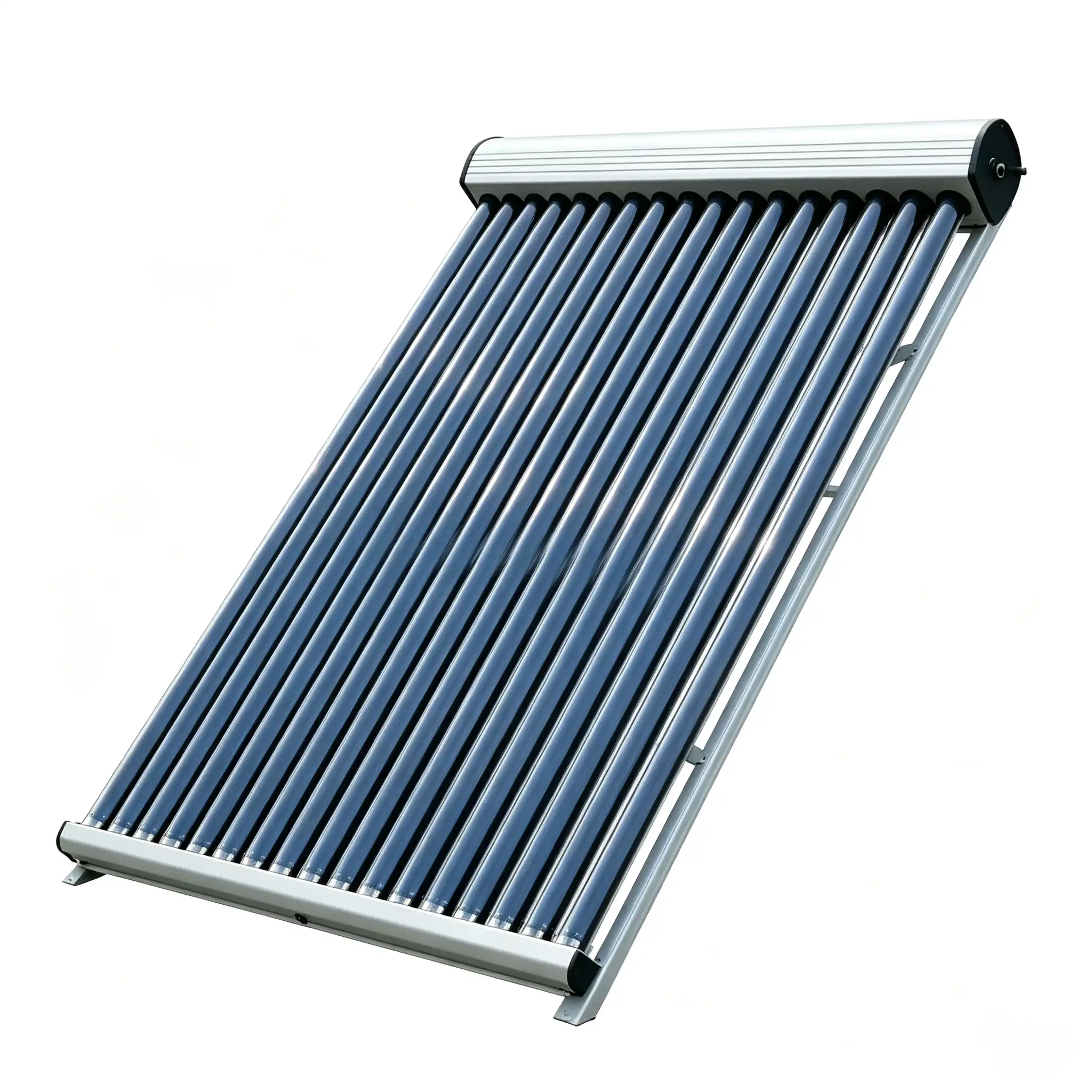
A direct-flow evacuated-tube collector in which solar-loop fluid circulates through a copper U-shaped tube inside each vacuum tube, transferring captured heat continuously to an external storage or heat-exchange system.
The absorber transfers solar heat to a metal fin and U-shaped pipe. Pumped solar fluid enters one leg, travels through the heated tube and returns through the other leg to the manifold.
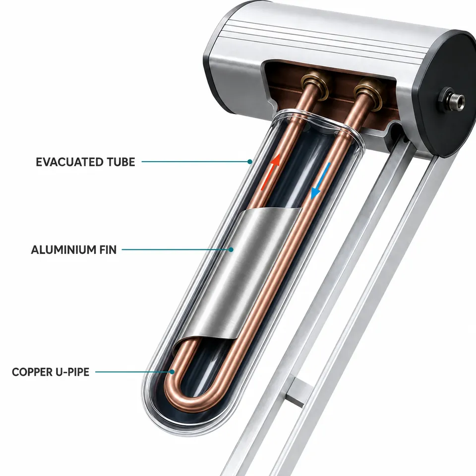
The selective absorber captures radiation inside the vacuum-insulated glass tube.
A heat-transfer fin conducts thermal energy from the absorber toward the metal flow path.
Cooler solar-loop fluid is pumped through the inlet side of the U-shaped tube.
Heated fluid returns through the outlet and carries energy to an external heat exchanger or tank.
Both use evacuated tubes, but their internal heat-transfer principles, hydraulic behaviour and maintenance considerations differ.
The heat-transfer medium moves through the U-pipe rather than relying on a sealed phase-change element.
Direct thermal transportThe evacuated glass envelope reduces convective loss around the absorber assembly.
Supports useful temperature liftA properly rated U-pipe module can be integrated into a pumped solar circuit.
System-level hydraulic controlDirect-flow heat transport is not based on gravity returning condensate inside a heat pipe.
Broader design discussionModules can be designed into parallel or series-parallel arrays subject to pressure-drop limits.
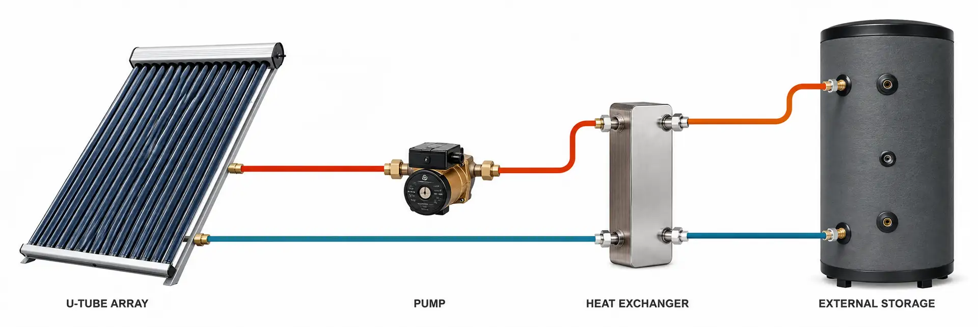
Matched to project loadThe collector loop can transfer energy through an external tank coil or plate heat exchanger.
Separates collector fluid from use waterA U‑tube collector is one part of a complete solar thermal installation. Its flow rate and pressure drop must be coordinated with the pump, piping, heat exchanger and array layout.
| Parameter | Preliminary Option / Reference | Confirmation Requirement |
|---|---|---|
| Collector Type | U‑tube direct-flow ETC | Do not label as heat pipe. |
| Heat-Transfer Tube | Copper U‑pipe option | Grade, diameter and wall thickness require approval. |
| Absorber Coupling | Metal heat-transfer fin | Material and contact design depend on model. |
| Evacuated Tube | Borosilicate glass option | Exact diameter, length and coating require confirmation. |
| Tube Quantity | Model-dependent module series | Publish only confirmed Cassky combinations. |
| Aperture / Gross Area | Model-dependent | Use tested reference areas for the exact model. |
| Manifold | Insulated metal housing | Header material and insulation must be specified. |
| Heat-Transfer Fluid | Water or water-glycol* | Compatibility and freeze protection require system review. |
| Working Pressure | Model-dependent | Use approved design and test pressure only. |
| Recommended Flow | Array-design dependent | Calculate from module performance and pressure drop. |
| Connections | Threaded / project option | Confirm standard, size and sealing method. |
| InstallationAngle | Project-dependent | Confirm yield, drainage, roof, wind and snow conditions. |
| Certifications | Destination-market option | List only certificates covering the exact model. |
External-storage systems for hospitality, residential blocks and institutional facilities.
Solar contribution to low-temperature hydronic loops after engineering evaluation.
Indirect heat delivery through a correctly selected exchanger and circulation system.
Application-specific preheating based on load temperature and operating schedule.
Discuss tube series, U‑pipe assembly, manifold, frame, connections, labels, manuals, packaging, pilot orders and rolling batch plans.
Common engineering and procurement questions about U‑tube direct-flow evacuated solar collectors.
No. U‑tube solar-loop fluid flows through a U-shaped pipe. Heat pipe collectors use a sealed phase-change pipe and condenser to transfer heat to manifold fluid.
No. It is a collector module requiring an external tank or load, pump station, controller, heat exchanger and safety equipment.
U‑tube architecture is intended for pumped closed-loop integration, but allowable pressure must be confirmed from the exact model's approved rating.
It may be suitable for selected designs. Fluid type, concentration, seals, metals, temperature limits and maintenance requirements must be reviewed together.
Yes, subject to model pressure drop, flow balance, permitted series length, pipe sizing and pump selection. Array hydraulics require engineering.
The glass envelope and internal hydraulic assembly are different service items. Because the U-pipe belongs to the fluid circuit, internal pipe service may require isolation and draining.
Potential options include module size, tube series, U‑pipe and fin construction, manifold, connections, frame, labels, documentation and packaging, subject to feasibility and order terms.
Provide application, country, climate, design temperatures, thermal load, roof area, system concept, quantity, certification needs and delivery schedule.
Cassky specializes in high-performance heat pump systems and solar energy solutions, providing reliable products and customized services for global distributors, engineering companies, contractors, and brand partners.
Tell us about your product or project requirements. Our team will contact you to discuss the next step.