
A solar hot water system for a hotel or apartment building must satisfy peak demand, not just average daily consumption. Therefore, project teams need to examine occupancy, draw timing, cold-water temperature, distribution losses, storage, backup capacity and water-hygiene controls before selecting collector quantity.
For available product architectures, start with the CASSKY evacuated-tube solar water heater platform and the companion Evacuated Tube Solar Hot Water System Project Guide. The pillar guide covers collector options, testing evidence and procurement risk. In contrast, this article focuses on building-level sizing and integration for hotels and multifamily apartment projects.
The calculations below support preliminary engineering. However, they do not replace local plumbing design, structural review, water-safety planning or a model-specific system simulation.
What Hotel and Apartment Buyers Care About
Project buyers usually focus on seven connected decisions.
| Buyer concern | Decision evidence |
|---|---|
| Will guests or residents receive hot water during peak periods? | Hourly draw profile, storage volume, recovery rate and backup capacity |
| How much energy can solar realistically provide? | Monthly climate data, collector coefficients, operating temperature and hourly simulation |
| Will the system maintain water pressure? | Peak flow, pipe size, static head, pump duty and tank pressure rating |
| Can the project control Legionella and scalding risks? | Water-management plan, storage temperature, return temperature and mixing-valve design |
| Can the solar field survive local weather? | Freeze strategy, stagnation strategy, wind load, snow load and mounting design |
| Will the system integrate with the existing plant? | Hydraulic schematic, control sequence and backup-heater data |
| Can the operator maintain it? | Service clearance, isolation valves, spare parts, monitoring and commissioning records |
A supplier cannot answer these questions from room count alone. Consequently, the RFQ must include both daily energy demand and peak operating conditions.
Hotel and Apartment Loads Are Different
Hotels and apartments may use similar solar collectors. However, their load profiles often differ.
Hotel demand characteristics

Hotels can create concentrated morning and evening shower peaks. In addition, kitchens, laundry rooms, spas and housekeeping may add separate loads.
Occupancy also changes by season and day of the week. Therefore, annual room occupancy does not describe the highest two-hour demand.
A hotel load study should separate:
- Guestroom showers and washbasins
- Kitchen hot water
- Laundry demand
- Housekeeping demand
- Spa or wellness facilities
- Staff accommodation
- Distribution and recirculation losses
If the laundry operates during the solar collection period, it may improve direct solar utilization. However, the EPC should not assume this benefit without an operating schedule.
Apartment demand characteristics
Apartment demand usually spreads across more hours. Nevertheless, weekday morning and evening peaks can still control tank and backup-heater selection.
Apartments also introduce commercial questions that hotels may not face:
- Central or individual energy billing
- Tenant responsibility for maintenance
- Different unit occupancy levels
- Future occupancy changes
- Unequal pipe lengths
- Multiple risers or pressure zones
- Phased construction
- Plant-room ownership and access
Therefore, one central system may suit a single-owner apartment building. In contrast, individual or zoned systems may suit developments with separate ownership and billing.
Solar Hot Water System Load Input Table
Use measured data whenever possible. Otherwise, label the value as a project assumption or sensitivity input.
| Input | Required information | Evidence status |
|---|---|---|
| Building type | Hotel, serviced apartment, dormitory or residential apartment | Project-confirmed |
| Rooms or units | Total and occupied during design period | Project-confirmed |
| Occupancy | Guests per occupied room or residents per unit | Measured or documented assumption |
| Hot-water allowance | Litres per person, room, unit or service activity | Measured or sensitivity input |
| Draw temperature | Temperature at fixture or process | Project-confirmed |
| Cold-water temperature | Monthly values and design minimum | Measured or climate-based |
| Hourly draw profile | At least hourly; shorter intervals help with sharp peaks | Metered, modeled or to be measured |
| Peak demand | Litres during the controlling one- or two-hour period | Project-confirmed |
| Storage temperature | Normal and sanitation operating targets | Water-management plan |
| Recirculation return | Flow, temperature and operating schedule | Hydraulic calculation |
| Pipe lengths | Supply and return lengths by riser or zone | Design drawing |
| Pipe insulation | Material, thickness and thermal properties | Specification |
| Solar resource | Irradiance on the proposed collector plane | Weather dataset |
| Collector orientation | Azimuth, inclination and shading | Site survey |
| Backup source | Boiler, heat pump, electric heater or district heat | Project-confirmed |
| Backup recovery time | Maximum time allowed after a peak or no-sun period | Owner requirement |
| Water quality | Hardness, chlorides, pH and conductivity | Laboratory analysis |
| Available roof area | Clear dimensions after access and setback allowances | Site survey |
| Structure | Roof loads, wind, snow and anchoring limits | Structural engineer |
| Plant-room space | Tank access, drainage, door size and service clearance | Site survey |
| Compliance basis | Plumbing, pressure, electrical and public-health requirements | Destination-market review |
Do not leave an unknown input unexplained. Instead, mark it “to be measured,” “supplier to confirm” or “for sensitivity analysis only.”
Calculating the Daily Hot-Water Energy
The basic useful-water load follows:
Q = m × 4.186 × ΔT ÷ 3,600
Where:
- Q represents thermal energy in kWh.
- m represents water mass in kg.
- 4.186 represents the approximate specific heat capacity of water in kJ/kg·K.
- ΔT represents the required temperature rise in °C.
This equation covers useful water heating. Therefore, the final plant load must also account for tank losses, distribution losses, heat-exchanger losses and control behavior.
Illustrative hotel calculation
The following scenario supports sensitivity analysis. It is not a completed CASSKY project or a product-performance claim.
Assume:
- Hotel size: 120 rooms
- Design occupancy: 75%, or 90 occupied rooms
- Guests per occupied room: 1.6
- Design guests: 144
- Assumed hot-water use: 50 litres per guest per day
- Delivered-water temperature: 45°C
- Cold-water temperature: 15°C
Daily mixed-water demand becomes:
144 guests × 50 L = 7,200 L/day at 45°C
The useful heating load becomes:
Q = 7,200 × 4.186 × (45 − 15) ÷ 3,600
Q = approximately 251.2 kWh/day
The 50-litre allowance is an illustrative assumption. Therefore, the project team should replace it with metered data, owner standards or an approved design basis.
Cold-water sensitivity
Cold-water temperature can materially change the result.
| Cold-water temperature | Delivered temperature | Daily volume | Useful heating load |
|---|---|---|---|
| 10°C | 45°C | 7,200 L | 293.0 kWh/day |
| 15°C | 45°C | 7,200 L | 251.2 kWh/day |
| 25°C | 45°C | 7,200 L | 167.4 kWh/day |
Consequently, a system sized from an annual-average inlet temperature may underperform during the coldest months.
Converting Delivered Water to Stored Hot Water
Suppose the project stores water at 60°C and mixes it with 15°C cold water to deliver 45°C water. A simplified mixing calculation gives:
Vhot = Vmixed × (Tmixed − Tcold) ÷ (Thot − Tcold)
Therefore:
Vhot = 7,200 × (45 − 15) ÷ (60 − 15)
Vhot = 4,800 litres at 60°C
However, 4,800 litres does not automatically equal the required tank volume. The final selection must consider:
- Peak draw timing
- Usable tank volume
- Tank stratification
- Minimum permitted storage temperature
- Heat-exchanger capacity
- Recirculation losses
- Backup recovery
- Solar-storage allocation
- Maintenance reserve
- Multiple-tank sequencing
For example, poor tank stratification can reduce usable capacity even when nominal volume appears adequate.
Checking the Peak Period
Daily energy does not define peak capacity. Therefore, the buyer should also calculate the controlling draw period.
Assume the hotel uses 3,000 litres at 45°C during a two-hour morning peak. With 15°C cold water:
Peak-period energy = 3,000 × 4.186 × (45 − 15) ÷ 3,600
Peak-period energy = approximately 104.7 kWh
If the system had to heat that water directly during the two-hour period, the average heating rate would reach:
104.7 kWh ÷ 2 hours = 52.3 kW
This value excludes distribution and storage losses. Moreover, the plant may need additional recovery capacity before the next peak.
If the project stores water at 60°C, the same simplified mixing relationship gives:
3,000 × (45 − 15) ÷ (60 − 15) = 2,000 litres at 60°C
Nevertheless, the EPC should treat this figure as an energy-equivalent volume rather than a final tank selection.
Estimating Solar Collector Area
First, define a preliminary solar contribution. Then, apply project-specific climate and collector data.
For the illustrative 251.2 kWh/day load, a 50% solar target equals:
251.2 × 50% = 125.6 kWh/day
The following values show sensitivity to assumed usable collector output.
| Assumed useful solar delivery | Indicative collector area |
|---|---|
| 2.0 kWh/m²/day | 62.8 m² |
| 2.5 kWh/m²/day | 50.2 m² |
| 3.0 kWh/m²/day | 41.9 m² |
These yields serve only as sensitivity inputs. They do not represent a CASSKY model rating or a guaranteed project result.
The European Commission’s PVGIS hourly-radiation tool provides downloadable solar-radiation and temperature data. However, the simulation must still apply the exact collector coefficients, inclination, shading, pipe losses and operating temperature.
For more detailed analysis, the NREL System Advisor Model help document describes a solar water-heating model that includes collector flow, heat-exchanger behavior, pipe losses, storage and differential pump control. Nevertheless, the engineer must confirm whether its system assumptions match the proposed architecture.
Selecting the System Architecture
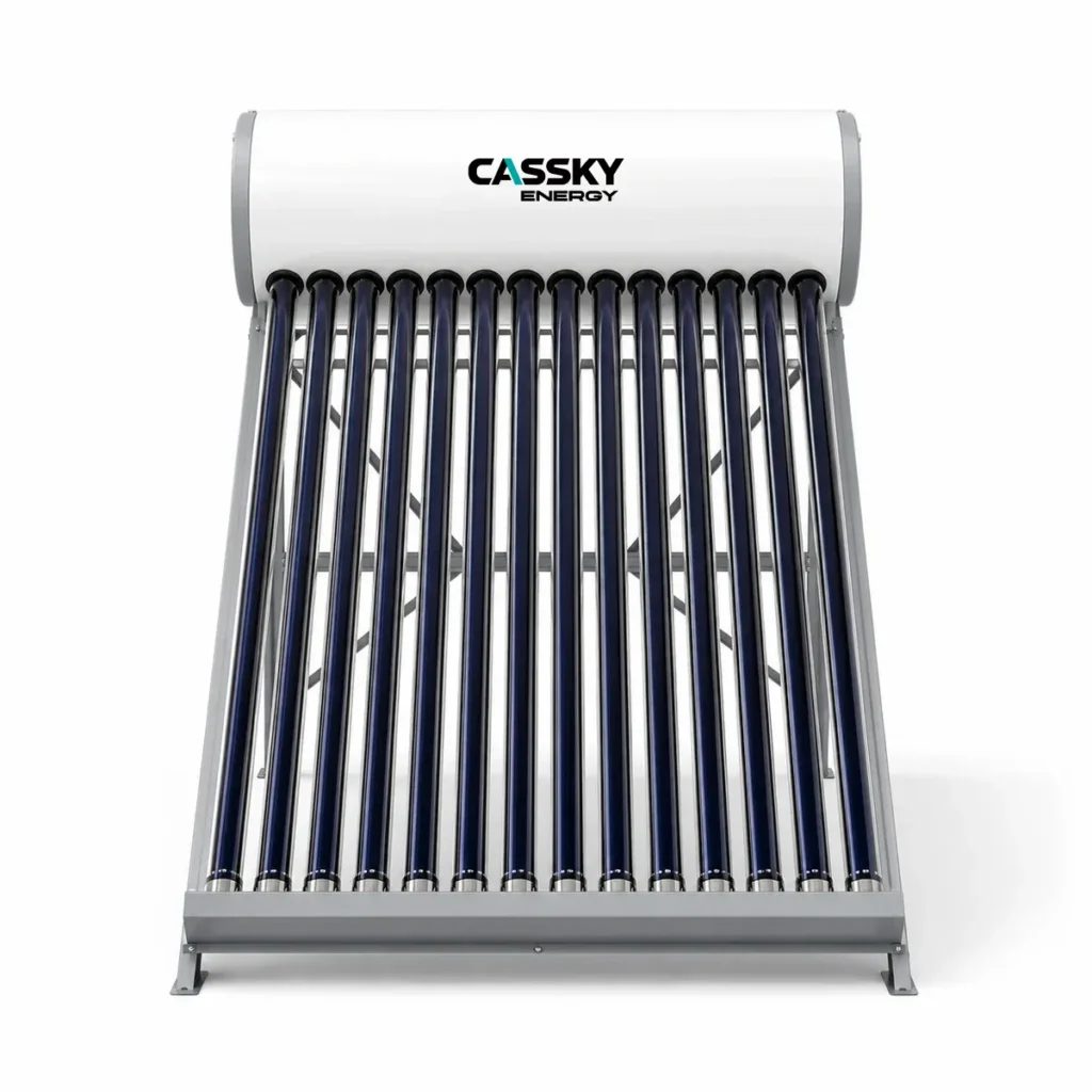
Hotels and apartments can use several system layouts. Therefore, the project team should select the architecture before fixing the collector quantity.
| Architecture | Conditions where it may fit | Main benefit | Main limitation |
|---|---|---|---|
| Central pumped indirect system | Hotels, towers and apartment blocks with a central plant room | Separates the collector fluid from potable water and supports centralized backup | Requires pumps, controls, balancing and commissioning |
| Solar preheat before existing boiler | Retrofit projects with usable boiler capacity | Reduces changes to the existing delivery system | Existing boiler and controls must accept variable inlet temperature |
| Zoned solar systems | Large buildings with several wings, risers or pressure zones | Shortens distribution runs and supports phased operation | Adds tanks, controls and maintenance points |
| Distributed pressurized units | Low-rise apartments, villas or detached accommodation blocks | Can reduce central distribution losses | Adds roof tanks, roof loads and individual service points |
| Direct thermosiphon systems | Simple, warm-climate, low-pressure applications | Uses natural circulation and fewer active components | Usually unsuitable for large centralized pressurized networks |
| Solar plus heat-pump backup | Projects with suitable electrical capacity and plant space | Can reduce fossil-fuel dependence | Requires integrated controls and correct heat-pump operating temperatures |
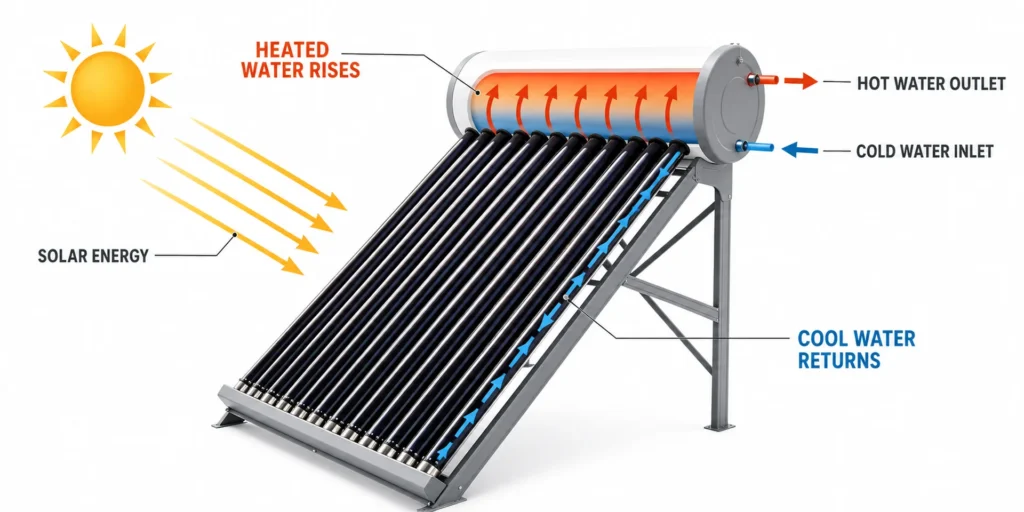
The CASSKY solar thermal range distinguishes complete water heaters from collector-only products for engineered storage and pumping systems. Therefore, large hotel projects should not treat a packaged rooftop heater as interchangeable with a central collector field. The CASSKY solar thermal product overview provides the product-family boundary.
Conceptual Central Solar Hot Water System
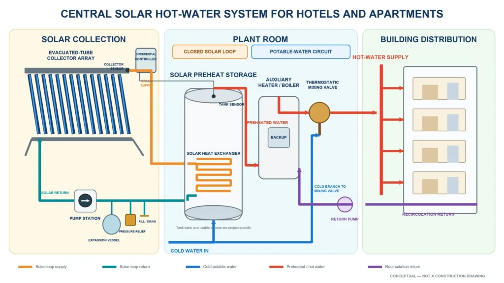
Figure 1. Conceptual central solar hot-water system for hotel and apartment projects. The closed solar loop transfers heat to solar preheat storage. Potable water then passes through the backup heater and mixing valve before entering the building. The recirculation loop returns separately to the auxiliary plant. Final pipe sizes, connections, valve locations, safety devices and setpoints remain project-specific.
How the solar loop operates
The collector pump circulates heat-transfer fluid through the evacuated-tube field and the solar heat exchanger. Meanwhile, a differential controller compares the collector and tank temperatures.
When useful solar energy becomes available, the controller starts the pump. Conversely, it stops circulation when the temperature difference becomes too small or when the storage tank reaches its approved limit.
The closed loop normally includes:
- Circulation pump
- Expansion vessel
- Pressure relief
- Fill and drain connections
- Air management
- Isolation valves
- Check valve where required
- Temperature sensors
- Flow measurement or balancing devices
The supplier must size these components for the actual loop volume, pressure, fluid and stagnation condition.
How the potable-water circuit operates
Cold potable water enters the solar preheat tank. Next, preheated water flows to the auxiliary heater.
The backup source raises the water to the required storage or supply temperature when solar input remains insufficient. Then, a thermostatic mixing valve limits the distribution temperature according to the project’s safety strategy.
Finally, the recirculation circuit keeps hot water available near remote fixtures. However, recirculation also creates a continuous heat load that the energy model must include.
Collector Field Design
A commercial collector field needs more engineering than a single domestic unit.
Collector performance data
Request the following data for the exact collector:
- Model and revision
- Gross and aperture areas
- Optical-efficiency term
- First- and second-order heat-loss coefficients
- Incidence-angle modifier
- Test flow and test fluid
- Pressure drop
- Maximum operating pressure
- Stagnation temperature
- Permitted installation angle
- Wind and snow limits
- Freeze-protection instructions
ISO 9806:2025 specifies methods for collector thermal performance, durability, reliability and safety testing. However, an ISO 9806 report applies to the tested collector, not automatically to the complete hotel system or annual project yield.
Parallel bank balancing
Large projects often connect several collector banks in parallel. Therefore, the hydraulic design must distribute flow evenly.
The EPC should check:
- Number of collectors per bank
- Pipe lengths to each bank
- Reverse-return or balancing-valve strategy
- Manufacturer flow requirement
- Total field pressure drop
- Pump operating point
- Fluid properties at minimum and maximum temperatures
- Air removal and drainage
- Isolation for service
Uneven flow can create hot banks, cool banks or early stagnation. Consequently, total pump flow alone does not prove correct field distribution.
Storage Tank Design
Solar storage must support both energy collection and peak service.
One tank or several tanks
A single tank can simplify pipework. However, large tanks may create access, lifting and replacement problems.
A tank bank may provide:
- Easier transport through plant-room doors
- Staged installation
- Partial service while another tank remains available
- Capacity expansion
- More flexible solar and backup zoning
Nevertheless, parallel tanks require hydraulic balancing. In contrast, series tanks require a clear control and draw sequence.
Protecting stratification
Thermal stratification keeps hotter water near the top and cooler water near the bottom. Therefore, it can improve collector operation and usable hot-water delivery.
Poor inlet design, excessive flow or incorrect tank connections can destroy stratification. As a result, the design should confirm:
- Cold-inlet diffuser arrangement
- Solar heat-exchanger position
- Hot-water outlet position
- Sensor height
- Backup-heater zone
- Recirculation return location
- Maximum tank flow
The nominal tank volume does not reveal these characteristics.
Backup Heating and Redundancy
Hotels normally require hot-water continuity during cloudy weather, maintenance and unexpected occupancy. Therefore, the backup system should cover a documented no-sun condition.
The design basis should state:
- Peak hot-water demand
- Available stored energy
- Required recovery time
- Minimum outdoor condition
- Utility availability
- Permitted service interruption
- Redundancy requirement
- Maintenance strategy
For example, an owner may require the backup plant to meet the full peak load without solar contribution. Another owner may accept reduced service during an equipment failure. These two projects need different equipment and costs.
In addition, the controls should prevent the backup heater from warming the entire solar-storage volume too early. Otherwise, the system may leave too little cool storage for useful solar input.
Recirculation and Distribution Losses
Hotels and tall apartment buildings often use continuous or scheduled hot-water recirculation. Therefore, distribution loss can form a substantial part of the plant load.
The calculation should include:
- Supply-pipe length
- Return-pipe length
- Pipe diameter
- Insulation thickness
- Ambient temperature
- Operating hours
- Supply and return temperatures
- Balancing-valve settings
- Pump heat
- Unoccupied branches
For example, a project may reduce tank size successfully but still consume excessive backup energy because long recirculation pipes lose heat continuously.
Consequently, the EPC should model water heating and distribution together.
Water Hygiene and Scalding Control
Hotels and centralized apartment systems need a documented water-management strategy. Solar operation must not weaken that strategy.
The CDC identifies low hot-water temperatures, stagnation, scale and reduced disinfectant residual as factors that can support Legionella growth. Moreover, low hotel occupancy can increase stagnation in unused rooms. The CDC hotel guidance recommends a building-specific water management program.
The CDC’s building-water monitoring guidance discusses storage above 60°C and circulation at or above 49°C as control guidance while also emphasizing anti-scald requirements. However, these values do not replace local regulations, the building’s risk assessment or an approved water-safety plan.
Therefore, the design should address:
- Storage-temperature control
- Recirculation return temperature
- Thermostatic mixing
- Point-of-use scald protection
- Dead legs
- Low-occupancy flushing
- Temperature monitoring
- Disinfectant residual where applicable
- Tank cleaning
- Scale and sediment control
A solar fraction target should never override the water-hygiene plan.
Freeze and Stagnation Boundaries
Freeze protection
Vacuum insulation does not protect every pipe, valve or manifold. Therefore, cold-climate projects need a complete freeze strategy.
Possible approaches include:
- Closed-loop antifreeze
- Drainback operation
- Approved circulation protection
- Heat tracing
- Seasonal drainage
- A product-specific cold-climate configuration
The design must also consider pump failure and loss of electrical power during freezing weather.
Stagnation protection
Hotels can experience low occupancy during sunny periods. Likewise, apartments may have reduced demand during holidays.
Consequently, the system should manage summer surplus through an approved combination of:
- Correct collector-to-storage ratio
- High-temperature-compatible components
- Drainback
- Controlled heat rejection
- Vacation mode
- Collector isolation
- Load diversion where permitted
- Documented shutdown procedure
Oversizing the collector field to improve winter output can increase summer stagnation. Therefore, the EPC should compare annual performance rather than optimize one design day.
Design Boundaries and Counterexamples
When a central system usually fits
A central pumped solar hot water system may fit when:
- One owner controls the plant and distribution.
- The building has a central boiler or heat-pump plant.
- The roof offers a usable collector area.
- The plant room can accommodate solar storage.
- The operator can maintain pumps, controls and water treatment.
- The project has regular year-round demand.
- The recirculation system already follows a water-management plan.
When a central system may not fit
A central system may provide limited value when:
- The building has very low or seasonal occupancy.
- Distribution losses approach the useful hot-water load.
- The roof has severe shading.
- The structure cannot support the collector system.
- The plant room lacks tank access.
- Separate apartment ownership requires individual billing.
- The project cannot maintain the solar fluid or controls.
- The backup plant cannot accept variable inlet temperatures.
Counterexample: low-rise apartment blocks
Consider six separate low-rise apartment blocks with long underground pipes to one central plant. A large central solar system may reduce collector count. However, underground distribution and recirculation losses may offset that benefit.
In this case, zoned or building-level systems may provide a better technical boundary.
Counterexample: seasonal resort hotel
A resort hotel may close during the sunniest part of the year. Therefore, a collector field sized for winter occupancy could experience extended summer stagnation.
A smaller field, controlled heat rejection or a seasonal shutdown strategy may provide a safer result than maximizing the nominal solar fraction.
Test Evidence and Project Performance
The buyer should keep component testing, system modeling and field acceptance separate.
| Evidence | What it supports | Important boundary |
|---|---|---|
| ISO 9806 collector test | Collector coefficients and applicable durability, reliability and safety results | Does not prove annual building yield |
| ISO 9459 system method | Performance of a defined solar water-heating system under stated procedures | Must match the system type and test scope |
| Computer simulation | Monthly or hourly project performance | Result depends on correct inputs and model assumptions |
| Factory quality checks | Product conformity before shipment | Does not confirm field installation |
| Field performance check | Collector-field operation under measured conditions | Does not replace long-term monitoring |
| Commissioning | Pumps, sensors, controls, temperatures and safety functions | Confirms initial operation, not lifetime performance |
ISO 9459-4 addresses component tests combined with computer simulation for annual energy evaluation. Meanwhile, ISO 9459-5 covers whole-system testing combined with simulation within its stated scope.
For larger collector fields, ISO 24194:2026 specifies procedures for checking solar thermal collector-field performance. Therefore, an EPC may reference it when defining a contractual field-performance check. However, the contract must still state the measurement conditions, instrumentation and acceptance tolerance.
Commissioning Checklist
The project should approve a commissioning plan before installation ends.
Documentation checks
Confirm:
- Approved hydraulic schematic
- Exact collector and tank models
- Valve and sensor schedule
- Controller sequence
- Pump duty point
- Heat-transfer fluid
- Pressure ratings
- Electrical supply
- Water-management requirements
- Backup-heater sequence
- Acceptance tolerances
Mechanical checks
Verify:
- Collector orientation and inclination
- Structural anchors
- Roof waterproofing
- Pipe support
- Insulation continuity
- Expansion-vessel connection
- Relief discharge route
- Service clearances
- Tank and pipe labeling
- Isolation-valve access
Hydraulic checks
Record:
- Static fill pressure
- Operating pressure
- Collector-loop flow
- Flow through each parallel bank
- Pump speed or setting
- Pressure drop
- Antifreeze concentration
- Fluid freeze point
- Air removal
- Leakage-test result
Control checks
Test:
- Collector sensor
- Tank sensor
- Pump start differential
- Pump stop differential
- High-temperature limit
- Freeze function
- Stagnation response
- Backup-heater enable
- Mixing-valve operation
- Alarm outputs
- Power-failure recovery
Distribution checks
Measure:
- Storage temperature
- Mixed supply temperature
- Recirculation return temperature
- Time to hot water at remote outlets
- Temperature at representative fixtures
- Balancing across risers
- Scald-protection operation
No-sun and solar-collection tests
First, test whether the backup source can satisfy the agreed service condition without solar input. Next, test solar collection during suitable weather.
The acceptance record should include:
| Test item | Acceptance basis |
|---|---|
| Collector-loop flow | Approved design schedule and supplier tolerance |
| Bank balancing | Project commissioning tolerance |
| Sensor accuracy | Comparison with calibrated reference |
| Pump control | Approved start and stop sequence |
| Backup recovery | Owner’s no-sun recovery requirement |
| Mixed outlet temperature | Water-safety plan and local regulation |
| Recirculation return | Approved temperature and balancing schedule |
| Safety devices | Functional test without uncontrolled discharge |
| Field output check | Contract method and measured weather conditions |
| Data logging | Complete and time-synchronized record |
Do not accept “system running” as the only result. Instead, require recorded flows, temperatures, pressures, settings and test conditions.
Information to Include in the RFQ
A project RFQ should include:
Load information
- Hotel rooms or apartment units
- Design occupancy
- Measured or assumed litres per person
- Daily hot-water volume
- Hourly draw profile
- Peak one- and two-hour demand
- Cold-water temperature
- Storage and delivery temperatures
- Kitchen, laundry or spa loads
Site information
- Project city and country
- Roof drawings
- Collector orientation
- Shading information
- Wind and snow conditions
- Structural limits
- Plant-room dimensions
- Pipe distances
- Water analysis
System requirements
- Central, zoned or distributed preference
- Target solar contribution
- Backup heat source
- Required recovery time
- Redundancy requirement
- Recirculation arrangement
- Monitoring points
- BMS protocol
- Freeze strategy
- Stagnation strategy
- Hygiene requirements
Supplier deliverables
- Model-specific datasheets
- Collector test evidence
- Pressure-drop data
- Hydraulic schematic
- Tank drawings
- Heat-exchanger data
- Pump selection
- Control sequence
- Electrical diagram
- Installation manual
- Commissioning procedure
- Spare-parts list
- Packing plan
- Warranty terms
CASSKY’s support page provides public catalogs and a channel for requesting model-specific manuals, drawings and compliance files. Document availability depends on the selected model, revision and destination market.
Frequently Asked Questions
Can a hotel size the system from room count?
No. Room count does not show occupancy, guests per room, peak timing, laundry demand or cold-water temperature. Therefore, the buyer needs a load profile.
Should solar cover 100% of the annual hot-water load?
Not automatically. A high annual solar target can create summer surplus and stagnation. Instead, compare annual energy, seasonal demand and lifecycle cost.
Can the project eliminate backup heating?
Most hotels and central apartment buildings need dependable service during cloudy weather, maintenance and peak demand. Therefore, removing backup heat usually creates an unacceptable service risk.
Should recirculation losses count in solar sizing?
Yes. The plant must replace heat lost from both supply and return pipes. Consequently, the model should include pipe length, insulation and operating hours.
Can the project use integrated rooftop tanks?
Small or distributed buildings may use them. However, a large central pressurized network usually needs an engineered collector field, external storage and controlled backup.
Does a collector certificate prove hotel performance?
No. Collector evidence supports component evaluation. Project output also depends on climate, temperature, storage, pipework, controls, occupancy and maintenance.
Request a Preliminary CASSKY Project Review
For preliminary solar hot water system selection, submit:
- Project city and country
- Hotel rooms or apartment units
- Design occupancy
- Daily and peak hot-water demand
- Hourly draw profile
- Cold-water and delivery temperatures
- Recirculation details
- Roof dimensions and photographs
- Plant-room dimensions
- Existing backup equipment
- Water-pressure and water-quality data
- Required test or certificate scope
- Target delivery date and quantity
CASSKY can then review whether an integrated, zoned or central collector arrangement matches the project boundary. After that, the buyer can request applicable model data, drawings, technical documents and quotation support.