
A successful water source heat pump installation starts before the equipment reaches the mechanical room. The installer must verify the source-water quality, sustainable flow, operating temperatures, hydraulic resistance, building load, terminal-water temperatures and maintenance access.
For a broader comparison of groundwater, engineered water-loop and ground-loop systems, read the Water and Ground Source Heat Pump System Design Guide.
This article has a narrower boundary. It explains how to integrate a water-to-water heat pump with an open water source or protected secondary loop. It focuses on water analysis, flow calculation, filtration, isolation heat exchangers, service clearances and commissioning. It does not replace well design, building-load calculation, local permitting or the complete procurement framework covered by the pillar guide.
What Buyers Should Verify Before Ordering
Project buyers usually focus first on capacity and price. However, installation risk is often controlled by five less visible questions:
- Can the water source provide the required flow in every operating season?
- Is the water chemically and physically compatible with the heat exchanger?
- Will source water pass directly through the heat pump, or will an isolation heat exchanger be used?
- Does the equipment room provide sufficient access for cleaning, testing and component replacement?
- Are commissioning acceptance criteria written into the contract?
A nominally correct heat pump can still suffer from low-flow alarms, heat-exchanger fouling, unstable outlet temperatures or excessive pump electricity if these questions remain unresolved.
Therefore, the final order should identify both the selected unit and its installation conditions.
Water Source Heat Pump Selection Input Table
The following information should be completed before final model selection.
| Selection input | Required project information | Status required before purchase |
|---|---|---|
| Project location | Country, city, elevation and applicable weather conditions | Buyer to provide |
| Building heating load | Design heating load at stated indoor and outdoor conditions | To be calculated |
| Building cooling load | Sensible and latent cooling load, including ventilation | To be calculated |
| Domestic hot water | Peak demand, daily volume, storage temperature and priority | Buyer and designer to confirm |
| Operating schedule | Daily hours, seasonal operation and simultaneous loads | Buyer to provide |
| Source type | Production well, lake, river, mine water, wastewater or engineered loop | Buyer to identify |
| Source temperature | Minimum, normal and maximum entering-water temperatures | To be measured or supported by site data |
| Sustainable source flow | Available flow under long-duration pumping conditions | To be measured |
| Static and pumping levels | Water levels at rest and at design flow | Required for well-pump selection |
| Water chemistry | Laboratory analysis covering the parameters in this article | To be measured |
| Sand and suspended solids | Concentration and expected seasonal variation | To be measured |
| Return arrangement | Discharge, reinjection or another approved method | Designer and authority to confirm |
| Heating-water temperature | Required supply and return temperatures | Project designer to confirm |
| Cooling-water temperature | Required chilled-water supply and return temperatures | Project designer to confirm |
| Source-side pressure loss | Pipes, strainers, valves, heat exchanger and fittings | To be calculated |
| Load-side pressure loss | Heat pump, buffer, terminals, valves and fittings | To be calculated |
| Electrical supply | Voltage, phase, frequency and available capacity | Buyer to provide |
| Control requirements | Standalone, cascade, BMS, Modbus or remote monitoring | Buyer to specify |
| Required quantity | Installed, duty and standby quantities | Supplier and buyer to confirm |
| Service limitations | Door size, lifting route, floor loading and maintenance space | To be measured |
A supplier cannot determine reliable pump duty or project-condition capacity from building area and required outlet-water temperature alone.
Recommended Installation Boundary
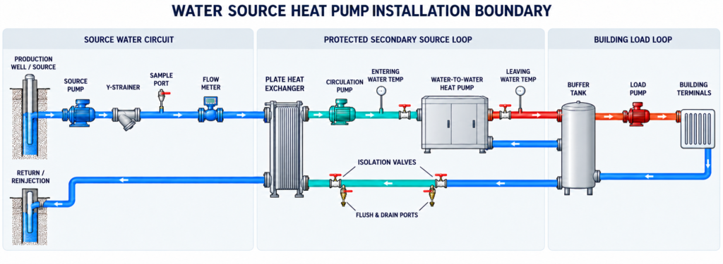
A water source heat pump installation may use either direct source-water connection or an isolation heat exchanger.
For projects with uncertain water chemistry, sediment or biological activity, an isolation plate heat exchanger can separate the raw source water from a protected closed loop connected to the heat pump. However, this arrangement introduces additional temperature approach, pressure loss, pumping power and cleaning requirements.
Figure 1. Conceptual water source heat pump installation boundary. The isolation heat exchanger protects the heat pump from direct source-water exposure, while measurement, flushing and service points support commissioning. The final arrangement remains project- and model-specific.
The diagram is not a construction drawing. In particular, valve quantity, bypasses, expansion equipment, air separation, strainers, heat-exchanger materials and safety devices must be completed by the project engineer.
Direct Source Water or Isolation Heat Exchanger?
Neither arrangement is universally correct.
| Decision factor | Direct source-water connection | Isolation heat exchanger |
|---|---|---|
| Heat-transfer path | Source water passes through the heat pump’s source heat exchanger | Raw water is separated from the heat pump by an intermediate exchanger |
| Temperature penalty | No intermediate exchanger approach | Additional temperature approach must be calculated |
| Pumping circuits | Potentially fewer components | Raw-water and protected-loop pumps may both be required |
| Fouling exposure | Heat pump exchanger receives the source water directly | Replaceable or cleanable isolation exchanger takes most source-water exposure |
| Water chemistry requirement | Must meet the exact heat pump manufacturer’s limits | Raw-water side must match the isolation exchanger material and treatment plan |
| Maintenance impact | Cleaning may require opening or chemically cleaning the heat pump circuit | Isolation exchanger may be easier to isolate and clean |
| Freeze protection | Model and source conditions determine requirements | Protected loop can use an approved antifreeze where necessary |
| Appropriate condition | Stable, analysed water expressly accepted for the exact model | Variable chemistry, sediment, corrosion or maintainability concerns |
| Inappropriate condition | Unknown water analysis or chemistry outside written limits | Unacceptable approach temperature, pressure loss or lifecycle cost |
The correct acceptance rule is straightforward: use direct connection only when the exact model documentation and a representative water analysis establish compatibility. A general statement that the water “looks clean” is not evidence.
Similarly, specifying an isolation exchanger does not remove all water risk. Its plate material, gasket material, fouling allowance, cleaning method and design velocity still require engineering review.
Water Quality Must Be Analysed
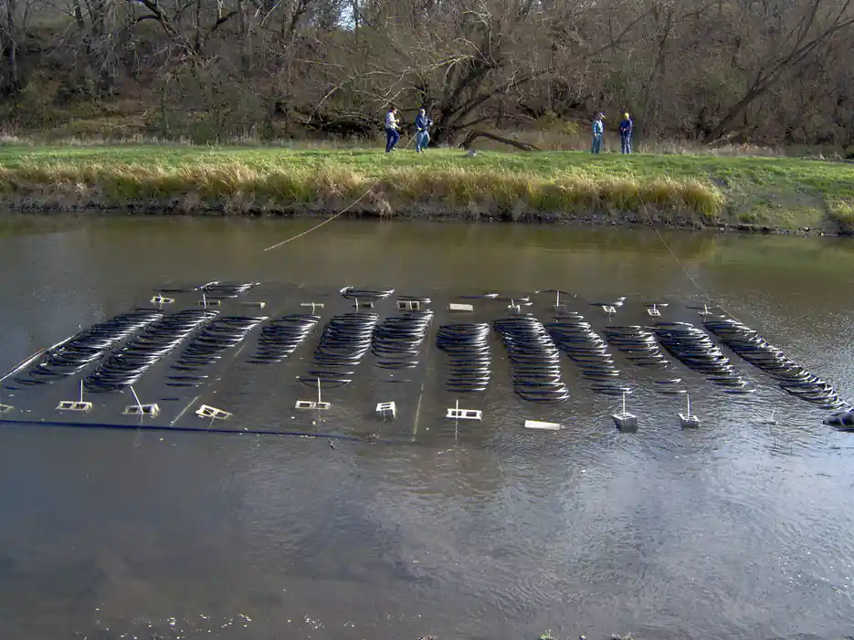
Source water can carry dissolved minerals, suspended solids, sand, corrosion products and biological material. These can cause scale, corrosion, erosion, blockage or biofouling.
The 2023 ASHRAE Handbook chapter on water treatment explains that water-treatment strategy depends on water chemistry, operating conditions, system metallurgy and manufacturer requirements. It also identifies scale, corrosion, deposition and biological growth as distinct problems requiring different controls.
Therefore, a water report should cover more than pH and hardness.
| Water parameter | Installation risk | Required decision |
|---|---|---|
| Temperature | Defines operating point and potential heat-pump capacity | Compare seasonal range with exact model envelope |
| pH | Influences corrosion and material compatibility | Supplier and heat-exchanger manufacturer to confirm limit |
| Total hardness | Indicates scale potential | Water-treatment specialist to assess |
| Alkalinity | Affects scaling indices and treatment selection | Include in chemistry review |
| Conductivity or TDS | Indicates dissolved ionic content | Compare with material and treatment limits |
| Chloride | Can accelerate corrosion of susceptible materials | Confirm allowable value for exchanger material |
| Sulfate | May contribute to corrosion or deposit risk | Specialist to assess |
| Iron and manganese | Can oxidise, precipitate and foul surfaces | Assess filtration and cleaning requirements |
| Silica | May form difficult deposits under some conditions | Treatment specialist to assess |
| Turbidity | Indicates suspended material | Establish filtration requirement |
| Total suspended solids | Can block strainers and foul exchangers | Establish separator or filter duty |
| Sand content | Can cause erosion and rapid blockage | Verify well development and sand separation |
| Dissolved oxygen | Influences corrosion in open systems | Include in materials review |
| Microbiological activity | Can produce biofilm and microbiologically influenced corrosion | Establish monitoring and treatment plan |
| Oil or process contamination | May attack seals or foul surfaces | Reject or treat according to specialist assessment |
The acceptance limits in this table are deliberately not generic numbers. They must come from the offered model, selected exchanger materials, water-treatment specialist and applicable local requirements.
A water sample taken once during drilling may also be insufficient. Where seasonal variation is credible, the engineer should determine whether samples are needed at different water levels, flows or times of year.
Strainers Are Not a Complete Water-Treatment System
A Y-strainer can intercept relatively large debris. However, it does not automatically remove fine silt, dissolved minerals, microorganisms or scale-forming chemistry.
Depending on the source, the installation may require:
- Well development before connection
- Sand separator or hydrocyclone
- Coarse strainer
- Automatic backwashing filter
- Side-stream filtration
- Isolation heat exchanger
- Chemical treatment
- Corrosion monitoring
- Sample points before and after treatment
- Differential-pressure measurement
- A documented cleaning procedure
Filter mesh should not be selected independently of the permitted pressure drop and heat-exchanger passage size. A finer filter may improve solids removal, but it can also block more rapidly and reduce system flow.
Consequently, the design should state the clean and dirty filter pressure drops, alarm threshold, cleaning access and spare-element requirement.
Open-Loop Water Requires Legal Review
A technically available water source is not necessarily legally usable.
For example, the U.S. Environmental Protection Agency identifies heat-pump return-flow wells as a category of Class V underground injection well. Its Class V well fact-sheet page provides a specific downloadable sheet for heat pump and air-conditioning return-flow wells.
Other jurisdictions may regulate:
- Well drilling
- Groundwater abstraction
- Maximum withdrawal
- Thermal discharge
- Reinjection
- Surface-water discharge
- Chemical additives
- Antifreeze
- Monitoring and reporting
- Well abandonment
These requirements vary by location. Therefore, neither CASSKY nor the equipment installer should be assumed to hold responsibility for permits unless that responsibility is explicitly stated in the contract.
A system should not be released for production based on an assumed future permit.
Calculate Flow from the Correct Heat Quantity
Source-side flow should be calculated from the heat transferred on the source side, not automatically from the building load.
For water:
Heat transfer = Mass flow × Specific heat capacity × Temperature difference
Therefore:
Mass flow = Heat transfer ÷ (Specific heat capacity × Temperature difference)
For pure water near normal HVAC temperatures, a preliminary specific heat value of approximately 4.186 kJ/kg·K can be used. Final calculations should use the properties at the design temperature and concentration.
Hypothetical Heating Example
This example is for calculation explanation only. It is not CASSKY model data or a project case.
Assume:
- Building heating output: 120 kW
- Heat pump COP at the actual source and load condition: 4.0
- Source-loop design temperature difference: 4 K
- Fluid: water
- Water specific heat: approximately 4.186 kJ/kg·K
The heat pump electrical input is:
120 kW ÷ 4.0 = 30 kW
Therefore, the heat extracted from the water source is:
120 kW − 30 kW = 90 kW
The required water mass flow is approximately:
90 ÷ (4.186 × 4) = 5.38 kg/s
At an approximate water density of 1 kg/L, this is about 5.4 L/s, or 19.4 m³/h.
This result is a preliminary thermal flow. It does not include a safety margin, plate heat-exchanger approach, fouling, fluid-property correction or the selected unit’s minimum and maximum flow limits.
If glycol is used in a protected secondary loop, use the actual mixture’s density, specific heat and viscosity. Do not reuse the pure-water result.
Pump Power Can Change the System Result
Available flow alone is insufficient. The pump must overcome the total dynamic resistance at that flow.
The pressure-loss calculation should include:
- Production-well lift
- Drawdown at design flow
- Pipe friction
- Strainers and filters
- Control and isolation valves
- Plate heat exchanger
- Heat pump
- Fittings and manifolds
- Reinjection pressure
- Required control-valve authority
- Dirty-filter or fouled-exchanger allowance
Using the previous hypothetical flow of 5.4 L/s, assume a closed-loop pressure requirement of 120 kPa and combined pump and motor efficiency of 65%.
The approximate electrical input is:
0.0054 m³/s × 120,000 Pa ÷ 0.65 = approximately 1.0 kW
This is only an illustrative pump calculation. The actual duty must come from the hydraulic model and selected pump curve.
For a groundwater pump, static lift, pumping water level and reinjection conditions can produce a much higher duty. Therefore, a project with an attractive heat-pump COP may still have disappointing system efficiency if source pumping energy is excessive.
Verify Sustainable Well Flow
A short pump test showing that water reaches the surface does not establish long-term system flow.
For a groundwater installation, request:
- Static water level
- Pumping water level
- Test flow
- Test duration
- Drawdown over time
- Recovery after shutdown
- Water temperature
- Sand production
- Seasonal groundwater information
- Reinjection test results
- Interference with nearby wells
- Well-pump curve and motor input
The U.S. Department of Energy’s geothermal purchasing guidance identifies water temperature, well flow and water quality as important groundwater-system properties.
The acceptance flow should be available at the required pumping level without unacceptable sand production or well interference. Additionally, the return arrangement must accept the same operating flow where reinjection is used.
Match Equipment Data to Project Conditions
The CASSKY All-in-One Water / Ground Source Heat Pump is publicly described as a reversible water-to-water platform for water or ground loops.
| Published series information | Public value | Evidence boundary |
|---|---|---|
| Heating capacity | 6–30 kW | Preliminary series range; exact model and condition to be confirmed |
| Cooling capacity | 5–26 kW | Preliminary series range; exact model and condition to be confirmed |
| Heating outlet water | Up to 60°C | Maximum outlet condition, not proof of capacity or COP at 60°C |
| Cooling outlet water | Down to 7°C | Source conditions and capacity remain model-specific |
| Reference heating COP | Up to 4.8 at B0/W35 | Series reference; not every model or water-source condition |
| Reference cooling EER | Up to 5.2 at W30/W7 | Series reference; units and test boundary to be confirmed |
| Electrical supply | 220–240 V single-phase or 380–415 V three-phase | Model-specific |
| Communication | RS485/Modbus RTU | Model-specific |
| Public application scope | Villas, apartments and light commercial buildings | Large commercial or modular arrangements require separate review |
For a water-source project, request performance at the actual minimum and maximum source temperatures. In addition, request capacity and input at the required heating, cooling and domestic-hot-water outlet temperatures.
A B0/W35 reference result cannot be substituted for a project operating at W10/W55. The source fluid, temperature lift and operating condition are different.
Laboratory Performance Is Not Installation Acceptance
ISO 13256-2:2021 covers testing and rating of factory-made water-to-water and brine-to-water heat pumps at defined source- and load-side conditions.
A report under this standard may substantiate:
- Heating or cooling capacity
- Equipment input power
- COP or efficiency at the stated condition
- Test fluid and flow
- Matched equipment configuration
However, it does not prove:
- Sustainable well yield
- Water chemistry compatibility
- Correct site flow
- Pumping energy
- Filter performance
- Borehole or reinjection capacity
- Building-load accuracy
- Site workmanship
- Annual system energy use
Similarly, electrical safety evaluation and market compliance are separate from performance testing. The current IEC base reference is IEC 60335-2-40:2024 with Amendment 1:2026, but the required national adoption and product scope depend on the target market.
Therefore, buyers should request the exact model’s reports and certificates rather than accepting a document for a related product family.
Minimum Hydraulic Components to Review
The exact arrangement depends on the project, but the design review should address:
- Isolation valves at serviceable components
- Flexible connections where appropriate
- Source- and load-side flow measurement
- Entering- and leaving-water temperature sensors
- Pressure or differential-pressure measurement
- Sampling points
- Strainer or filter
- Isolation plate heat exchanger where required
- Air separator and automatic air removal on closed loops
- Expansion vessel
- Fill, flush and drain connections
- Pressure-relief protection
- Low-flow protection
- Freeze protection
- Check valves where reverse flow is possible
- Balancing valves or automatic flow control
- Buffer tank where justified by the control analysis
- Floor drain or controlled drainage route
- Vibration isolation where required
- Condensation insulation on cold surfaces
A flow switch is a protective device. It does not prove that the design flow has been achieved. Commissioning should still measure actual flow or derive it using an accepted calibrated method.
Does Every Installation Need a Buffer Tank?
No. A buffer tank should be based on system volume, minimum unit output, minimum compressor runtime, zoning and hydraulic configuration.
It is more likely to be required when:
- The building load can fall below the heat pump’s minimum output
- Zone valves sharply reduce active flow
- The heat pump requires constant flow while the terminal circuit is variable flow
- Several modules operate in stages
- Domestic-hot-water priority changes the active circuit
- The existing system volume is too low
- Short cycling is otherwise expected
However, an oversized or poorly connected tank can add heat loss, cost and control complexity. Therefore, tank volume and connection method should be calculated rather than copied from another project.
Service Access Must Be Designed, Not Assumed
Equipment-room access affects installation, commissioning and future repair. A cabinet that fits between two walls may still be unserviceable.
Before approving the layout, confirm access for:
- Electrical-panel opening
- Controller and sensor replacement
- Filter or strainer removal
- Plate heat-exchanger cleaning
- Pump removal
- Compressor replacement
- Refrigerant service
- Drainage and flushing hoses
- Valve operation
- Water sampling
- Insulation removal and reinstatement
- Lifting equipment
- Complete unit replacement
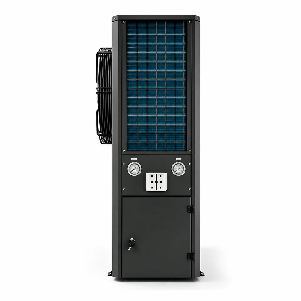
There is no universal clearance that can safely be applied to every model. Request a dimensioned installation drawing for the offered unit and identify the service side, connection side and component-removal paths.
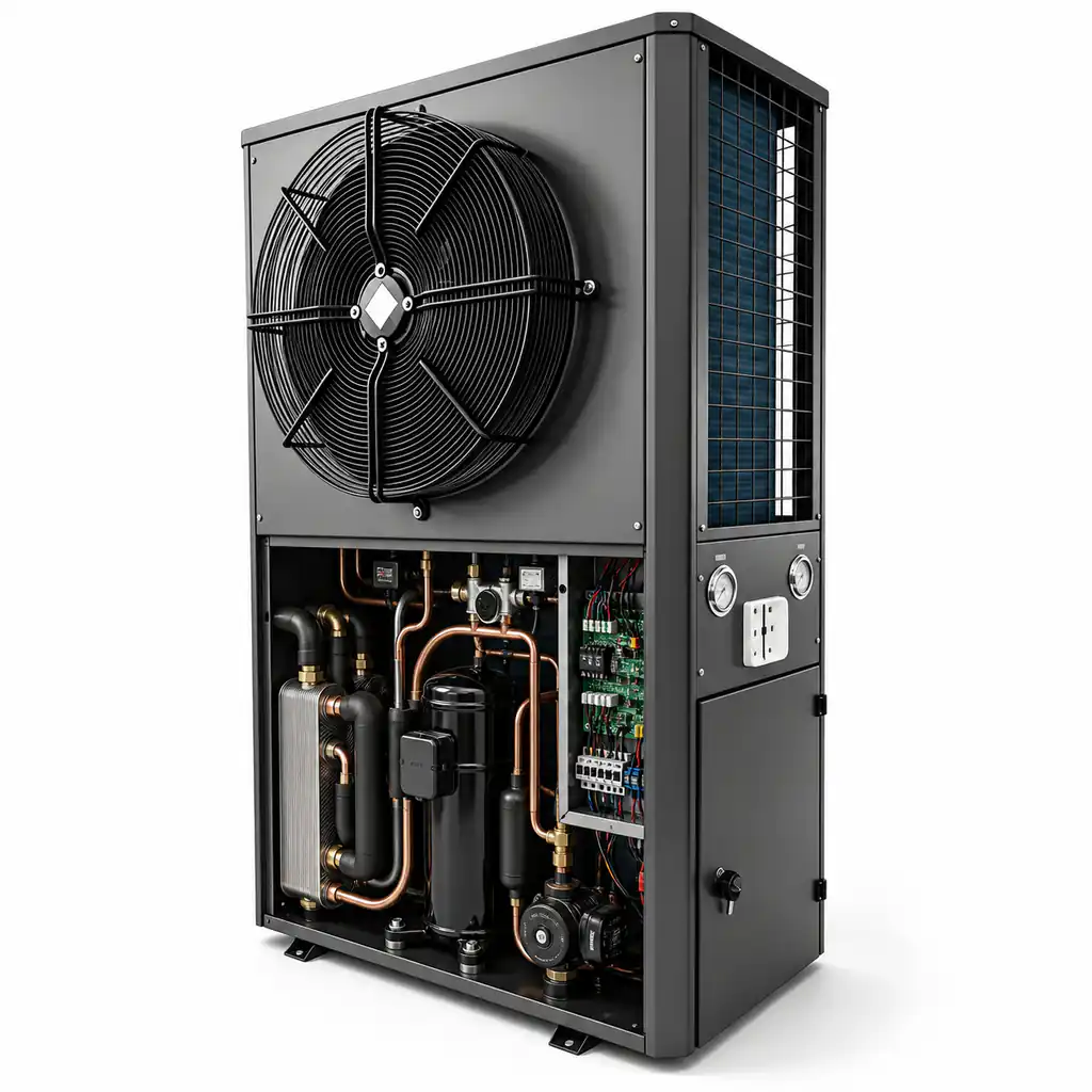
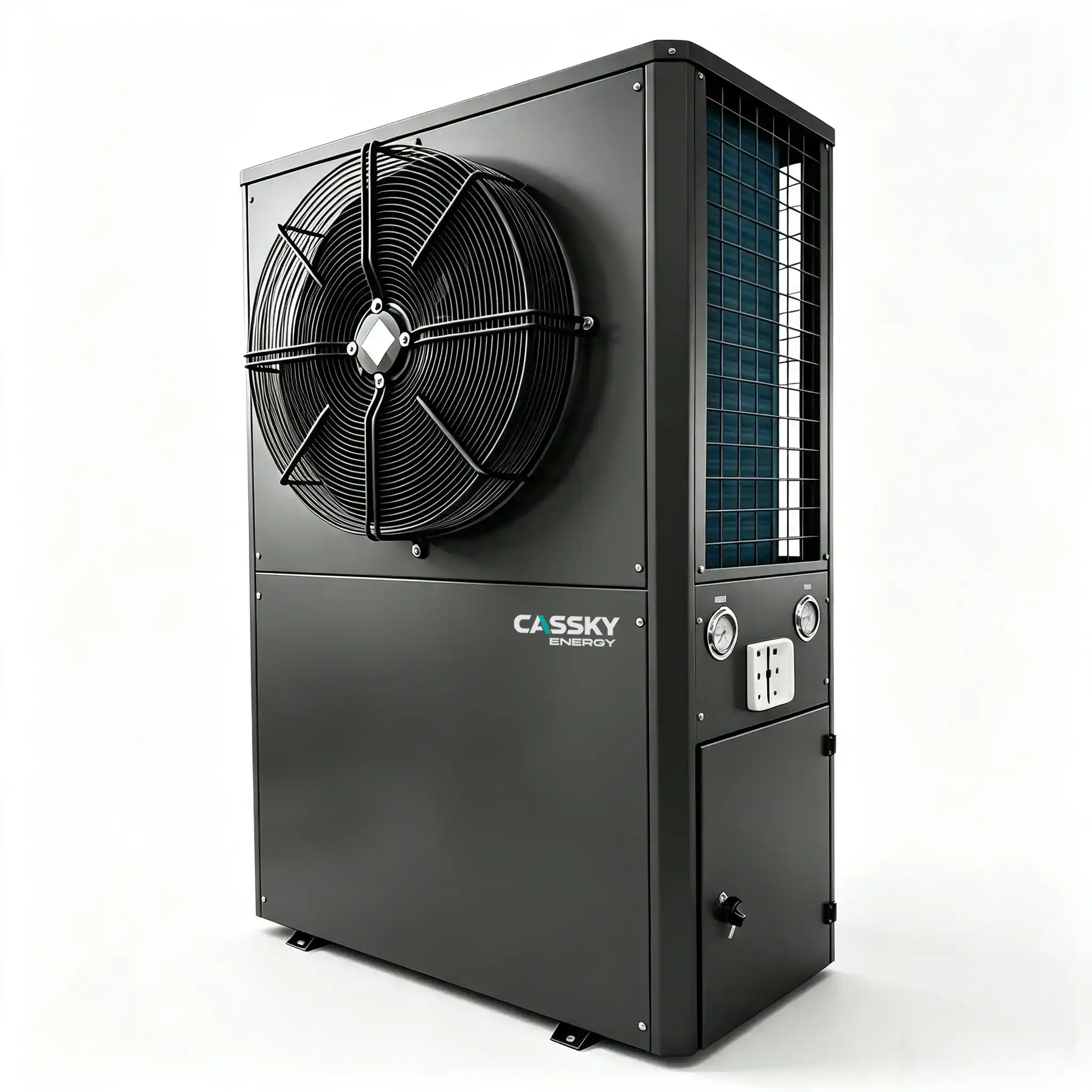
The public CASSKY product page shows cabinet and internal-layout views, but those images do not define contractual clearances. Exact model drawings should be requested before fixing walls, pipes, cable trays or adjacent equipment.
Common Layout Errors
Pipes Block the Service Panel
A pipe may connect correctly while preventing electrical or compressor access. Route headers outside the documented service zone.
The Strainer Cannot Be Removed
Allow space to withdraw the strainer screen without cutting pipework. Also provide isolation and a safe drainage route.
The Plate Heat Exchanger Has No Cleaning Connections
If fouling is foreseeable, provide valves and ports for cleaning, flushing and differential-pressure measurement.
The Flow Meter Is Installed in Disturbed Flow
Respect the meter manufacturer’s straight-run, orientation, grounding and fluid requirements. Otherwise, the displayed value may not be reliable.
Sensors Are Installed Far from the Equipment
Temperature sensors used for acceptance should represent the fluid entering and leaving the heat pump or heat exchanger. Long uninsulated pipe runs can distort the result.
Drainage Is Ignored
Strainer cleaning, sampling, flushing and component removal release water. The plant room needs a controlled drainage plan rather than reliance on temporary buckets.
Installation Design Boundaries
Responsibility should be assigned explicitly.
| Design package | Typical responsible party | Minimum deliverable |
|---|---|---|
| Building loads | HVAC consultant or project engineer | Heating, cooling and DHW load report |
| Source feasibility | Hydrogeologist or qualified water-source designer | Flow, temperature, chemistry and permit assessment |
| Wells and reinjection | Licensed local specialist | Well design, pump test and acceptance records |
| Heat pump selection | Supplier with project engineer review | Model and multi-condition performance |
| Water treatment | Qualified water-treatment specialist | Limits, treatment, monitoring and maintenance plan |
| Isolation heat exchanger | System designer | Material, duty, approach temperature and pressure loss |
| Hydraulics | Project mechanical engineer | Flow, pipe sizing, pump head and control valves |
| Electrical works | Electrical engineer or contractor | Supply, protection, isolation and cable schedule |
| Controls | Controls contractor and equipment supplier | Sequence, points list and communication boundary |
| Commissioning | Named commissioning party | Test procedure, calibrated records and report |
If the supplier provides only the heat pump, it should not be assumed to guarantee well flow, source chemistry, pump energy or complete building performance.
Conversely, an installer should not change the approved source fluid, design flow or control sequence without confirming the effect on the heat pump.
Pre-Start Commissioning Checklist
Do not energise the compressor merely because the pipework is full.
| Pre-start check | Acceptance condition |
|---|---|
| Exact model | Nameplate matches approved schedule and electrical supply |
| Shipping and installation condition | No visible transport or installation damage |
| Service clearance | Meets the model-specific approved layout |
| Pipe connections | Source and load circuits connected to the correct ports |
| Water analysis | Current report reviewed against written equipment and exchanger limits |
| Strainers and filters | Correct direction, clean condition and accessible removal |
| System flushing | Construction debris removed and records available |
| Pressure test | Completed at the specified test pressure and duration |
| Water treatment | Correct treatment and concentration documented |
| Antifreeze | Type, concentration and freeze protection measured |
| Air removal | Closed loops fully purged |
| Expansion equipment | Pre-charge and connection verified |
| Source flow | Measured and within the exact model’s permitted range |
| Load flow | Measured and within the exact model’s permitted range |
| Pumps | Rotation, duty point and electrical input checked |
| Sensors | Location and plausible reading confirmed |
| Electrical protection | Breaker, cable, earth and isolation verified |
| Phase sequence | Confirmed for three-phase equipment |
| Controller settings | Match the approved design sequence |
| Valves | Correct operating positions marked |
| Drainage | Safe drainage route available |
| Permits | Required abstraction, discharge or reinjection approvals available |
Any failed item should be corrected or formally accepted through the project’s deviation process before operation.
Functional and Performance Commissioning
After start-up, record stable operation in each required mode.
Source-Side Measurements
- Entering-water temperature
- Leaving-water temperature
- Actual flow
- Pressure drop
- Source-pump input
- Filter differential pressure
- Well level and drawdown where applicable
- Return or reinjection condition
Load-Side Measurements
- Entering-water temperature
- Leaving-water temperature
- Actual flow
- Pressure drop
- Load-pump input
- Buffer-tank temperatures
- Terminal supply and return temperatures
Equipment Measurements
- Compressor input
- Total unit input
- Heating or cooling output
- Field COP under the agreed measurement boundary
- Minimum-load behaviour
- Start and stop sequence
- DHW changeover
- Cascade and lead–lag operation
- Alarm and protective functions
- Modbus or BMS communication
Protection Tests
- Low-flow protection
- Source-temperature limit
- Load-temperature limit
- High- and low-pressure protection
- Sensor-failure response
- Pump interlock
- Power-recovery behaviour
- Emergency shutdown
ASHRAE/IES Standard 202-2024 provides a framework for defining commissioning responsibilities, procedures, documentation and acceptance against the Owner’s Project Requirements.
A start-up sheet containing only refrigerant pressures and an “operating normally” statement is not sufficient evidence of project performance.
Define the Site COP Boundary
Field COP can be calculated in several ways. Therefore, the contract must state which electrical inputs are included.
Possible boundaries include:
- Heat pump compressor and internal controls only
- Complete heat pump unit
- Heat pump plus source-loop pump
- Heat pump plus source- and load-side pumps
- Complete system including well pump, terminal fans and auxiliary heaters
These results are not interchangeable.
Additionally, the measurement plan should state:
- Flow-meter accuracy
- Temperature-sensor accuracy
- Sensor position
- Stabilisation period
- Sampling interval
- Treatment of cycling
- Included electrical loads
- Allowed test tolerance
Without this boundary, a site COP value may appear precise while remaining contractually ambiguous.
Handover Documents
The project handover package should include:
- Approved equipment schedule
- Exact model datasheet: request
- Applicable test reports and certificates: request
- Installation and operation manual: request
- Electrical diagram: request
- Hydraulic connection diagram: request
- Controller and Modbus documentation: request
- Water analysis
- Pump-test report
- Water-treatment specification
- Flushing and pressure-test records
- Antifreeze concentration record
- Pump curves and selected duty points
- Flow and temperature commissioning results
- Control sequence
- Alarm test records
- As-built drawings
- Valve schedule
- Spare-parts list
- Maintenance schedule
- Contact and escalation information
Requesting these documents does not mean every document is publicly downloadable. Model-specific files should be confirmed with CASSKY for the exact offered model and target market.
When This Installation Approach Is Appropriate
A protected water-source installation is more appropriate when:
- The source has verified temperature and sustainable flow
- Water chemistry can be managed
- Abstraction and return are legally permitted
- Source pumping energy remains acceptable
- The mechanical room can accommodate the heat pump and service components
- The project has qualified water, hydraulic and controls designers
- Long-term filtration and cleaning responsibilities are assigned
- Required heating and cooling temperatures fall within the selected model’s envelope
An isolation heat exchanger is particularly relevant where maintainability or source-water exposure presents a material risk.
When It May Be Inappropriate
A water-source heat pump may be a poor choice when:
- Sustainable flow has not been demonstrated
- Reinjection capacity is uncertain
- Water chemistry is incompatible with available exchanger materials
- Sand production remains uncontrolled
- Pumping head eliminates the expected energy benefit
- Local permits cannot be obtained
- The plant room prevents required maintenance
- The building requires water temperatures outside the verified equipment envelope
- No party accepts responsibility for water treatment
- Project economics depend on an unverified COP that excludes major pumps
For example, a deep well with stable temperature may initially appear attractive. However, if the production and reinjection pumps require substantial power, a closed ground loop or another heat source may provide a better whole-system result.
Frequently Asked Questions
Can groundwater flow directly through the heat pump?
Only when the exact model permits direct connection and a representative water analysis meets its written limits. Otherwise, an isolation heat exchanger may reduce equipment exposure.
How much source-water flow is required?
It depends on source-side heat transfer, permitted temperature difference, fluid properties and the selected model’s flow range. Do not calculate it from nominal building capacity alone.
Is a flow switch sufficient for commissioning?
No. A flow switch normally confirms only that flow is above or below its switching threshold. Measure actual flow for commissioning.
Does an isolation heat exchanger eliminate water-treatment requirements?
No. Raw-water fouling, corrosion and biological activity still affect the isolation exchanger. The protected loop also requires appropriate cleaning, filling and corrosion control.
Can a larger pump solve low-flow problems?
Not automatically. A larger pump can increase electricity use, noise, erosion risk and control instability. First verify the hydraulic calculation, restrictions, well yield and permitted equipment flow.
How much clearance does a water source heat pump need?
Clearance is model-specific. Request the installation drawing and check panel opening, filter removal, pump access, component lifting and whole-unit replacement routes.
Can published COP predict annual site performance?
No. Published COP applies to a defined laboratory condition and equipment boundary. Annual site performance also depends on water temperatures, loads, pumps, terminals, controls and operating hours.
Submit Project Data for Preliminary Selection
For preliminary CASSKY selection and integration review, provide:
- Project country and city
- Building type and operating schedule
- Heating, cooling and DHW loads
- Minimum and maximum source-water temperatures
- Sustainable source flow
- Static and pumping water levels
- Water-analysis report
- Sand and suspended-solids information
- Discharge or reinjection method
- Required heating and cooling water temperatures
- Source- and load-side design flow
- Estimated pressure loss
- Proposed direct or isolated connection
- Electrical supply
- Unit quantity and redundancy
- Mechanical-room drawing
- BMS or Modbus requirements
- Required certificates, test reports and technical documents
CASSKY can use these inputs to review a candidate model and identify the model-specific documents that must be requested. Final well, water-treatment, hydraulic, electrical, control and regulatory design should be completed by qualified project professionals.