
An evacuated tube solar hot water system can face two opposite design conditions. In winter, trapped water can freeze and damage exposed components. In summer, the collector field can produce heat when the building has nowhere to use or store it.
Therefore, buyers should not approve a system only because the supplier describes the vacuum tubes as suitable for cold weather. The vacuum reduces heat loss from the absorber. However, it does not automatically protect manifolds, pipes, valves, pumps, heat exchangers or rooftop tanks from freezing.
For the wider product-selection, testing and RFQ framework, use the companion Evacuated Tube Solar Hot Water System Project Guide and the CASSKY evacuated-tube solar water heater platform. This article has a narrower role: it explains how to choose and integrate freeze and stagnation protection for actual project conditions.
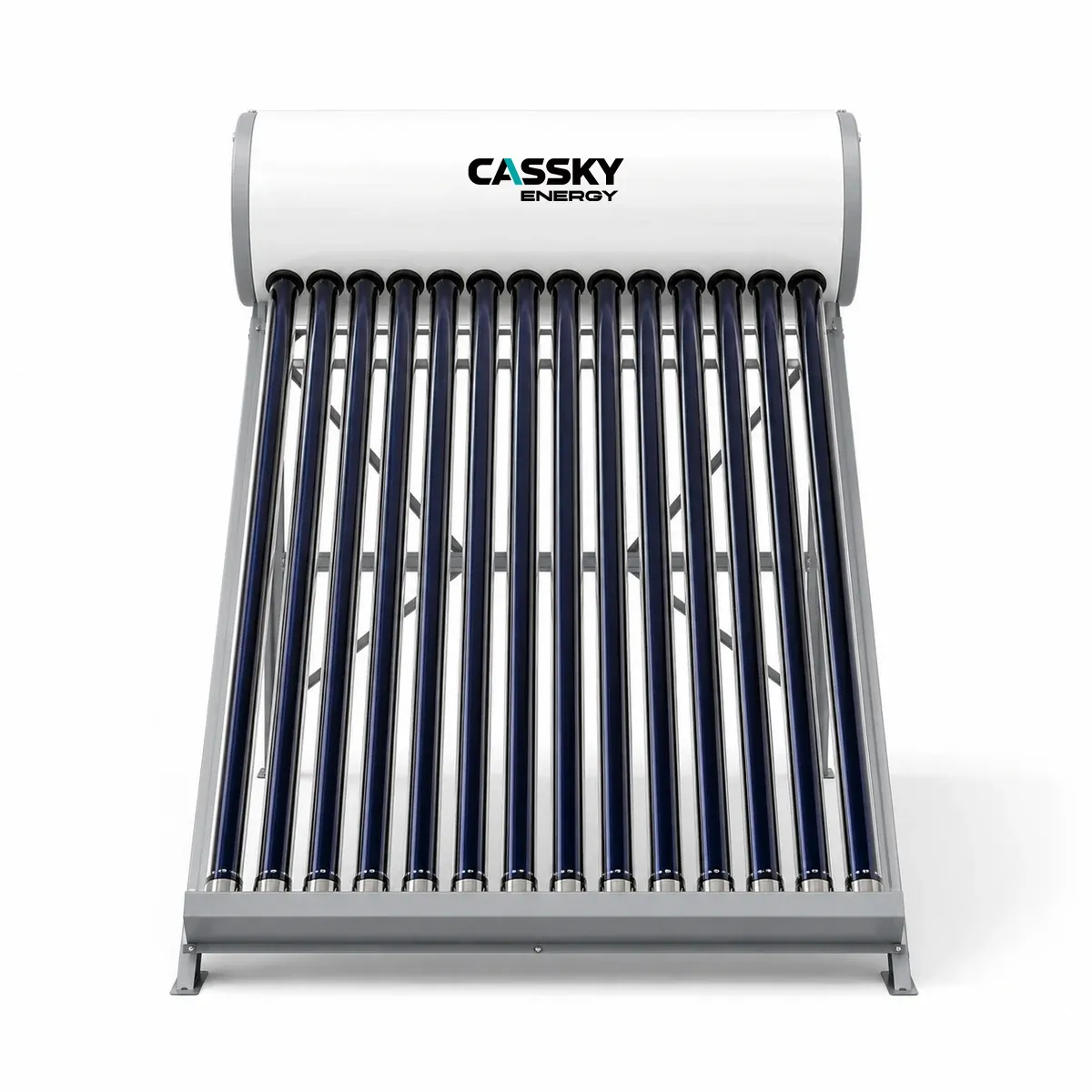
Four Approval Gates
A project buyer should not approve the proposed design until it passes four gates.
| Approval gate | Required evidence |
|---|---|
| Freeze protection | The proposed architecture covers the design minimum temperature and expected power-outage duration |
| Stagnation protection | The collector field, fluid, vessel, valves, insulation and controls can tolerate a no-load condition |
| Component compatibility | Every component carries suitable pressure, temperature, fluid and material limits |
| Commissioning proof | The installer measures fluid concentration, flow, pressure, controls, drainage and alarm functions |
A collector test report supports component evaluation. Nevertheless, it cannot confirm the freeze or stagnation protection of the installed pipework.
What Freezing Means for a Solar Thermal System
Water expands when it freezes. Consequently, trapped water can damage manifolds, tubes, coils, valves and pipe fittings.
The risk depends on more than the lowest air temperature. For example, rooftop pipework may cool faster than sheltered equipment in the plant room.
The freeze review should include:
- Design minimum ambient temperature
- Duration below freezing
- Wind exposure
- Night-sky cooling
- Pipe insulation
- Water or heat-transfer fluid
- Fluid concentration
- Fluid age
- Power reliability
- Pump availability
- Sensor location
- Drainability
- Trapped sections
- Rooftop tank location
A short overnight frost and a three-day power outage at −20°C create different design requirements.
What Stagnation Means
Stagnation occurs when the collector absorbs solar energy but the system cannot move useful heat into storage or a load. For example, the storage tank may reach its upper temperature limit, the pump may stop or the building may close during a sunny period.
As the collector temperature rises, part of the heat-transfer fluid may boil. Pressure and steam can then extend beyond the collector into connecting pipework.
The IEA Solar Heating and Cooling Programme reports that collector emptying behavior, pipe geometry and residual fluid strongly influence stagnation stress. In particular, trapped liquid can experience prolonged high temperatures and accelerate glycol degradation. The report also identifies pipe sags and unfavorable collector geometry as potential contributors to poor emptying behavior. See the IEA SHC Task 26 stagnation report.
Therefore, pressure relief alone does not provide a routine stagnation strategy. It acts as a safety device after pressure reaches its set condition.
Freeze and Stagnation Design Input Table
The following information should accompany a technical inquiry.
| Input | Information required | Evidence status |
|---|---|---|
| Project location | City, country and altitude | Project-confirmed |
| Design minimum temperature | Local code value and selected design basis | Project-confirmed |
| Freeze duration | Expected hours or days below the design threshold | Climate-based |
| Power outage | Maximum outage duration that the design must tolerate | Owner requirement |
| Collector model | Exact architecture and fluid path | Supplier to confirm |
| Collector fluid volume | Volume per module and total field | Supplier to confirm |
| External pipe volume | Supply and return pipe volume | Engineer calculation |
| Total loop volume | Collector, pipe, heat exchanger and accessories | Engineer calculation |
| Heat-transfer fluid | Product name, concentration and batch | Supplier and installer record |
| Fluid protection curve | Freeze, burst, boiling and expansion data | Fluid manufacturer |
| Fill temperature | Fluid temperature during charging | Commissioning record |
| Static height | Vertical distance between system components | Site drawing |
| Fill pressure | Cold fill pressure at a stated location | Engineer calculation |
| Relief setting | Valve setting and applicable tolerance | Supplier to confirm |
| Expansion vessel | Nominal volume, pre-charge and temperature limit | Supplier to confirm |
| Collector stagnation temperature | Exact model and test basis | Collector report |
| Component temperature limits | Pump, valve, seal, insulation and vessel limits | Component datasheets |
| Pipe geometry | Slopes, high points, low points and traps | Installation drawing |
| Drainback reservoir | Volume, location and operating level | Design-specific |
| Summer demand | Daily and hourly minimum load | Owner data |
| Maximum no-load period | Expected closure or low-occupancy period | Owner data |
| Storage limit | Maximum permitted tank temperature | Supplier and water plan |
| Heat rejection | Available load or rejection method | Project-specific |
| Control sequence | Freeze, high-limit, alarm and recovery logic | Approved controls document |
If the project team lacks a value, it should state “to be measured,” “supplier to confirm” or “for sensitivity analysis only.”
Comparing Protection Architectures
The design should start with one coherent primary-loop architecture.
| Protection architecture | More suitable conditions | Main advantage | Critical limitation |
|---|---|---|---|
| Pressurized antifreeze loop | Cold climates, complex roofs and pipework that cannot drain completely | Fluid can remain in exposed collectors and pipes during freezing weather | Fluid concentration, ageing, expansion and stagnation temperatures require control |
| Drainback loop | Projects with continuous pipe slope and a protected reservoir | Exposed collectors and pipes empty when the pump stops | Any sag, trap or non-draining section can defeat protection |
| Direct water thermosiphon | Warm climates with limited freezing risk | Simple natural circulation | Water remains exposed to freezing unless the exact system includes verified protection |
| Active freeze circulation | Mild and short freezing events with reliable power and controls | Uses stored heat to protect exposed components | Power loss, pump failure or depleted storage can remove protection |
| Electric heat tracing | Local pipe, valve or drain protection | Targets specific exposed areas | Depends on power, controls and installation quality |
| Controlled heat rejection | Projects with a dependable summer heat sink | Reduces high-limit events | Adds equipment, controls and operating energy |
| Collector shading or isolation | Seasonal sites with planned shutdown procedures | Reduces solar input | Requires safe access, approved materials and an operating procedure |
The U.S. Department of Energy’s solar thermal guidance distinguishes drainback, antifreeze and active circulation approaches. It also warns that circulation-based freeze protection depends on electrical power. See the downloadable DOE solar thermal design guide.
Two Alternative Primary-Loop Designs
Figure 1. Two alternative primary-loop architectures. A pressurized antifreeze loop keeps a declared heat-transfer fluid in the collector circuit, while a drainback system empties exposed collectors and pipes when the pump stops. Select one verified architecture; do not combine details without manufacturer and engineer approval.
Option A: pressurized antifreeze loop
A pump circulates a water-and-antifreeze mixture or another approved heat-transfer fluid through the collector and storage heat exchanger.
The design must coordinate:
- Fluid product
- Fluid concentration
- Cold fill pressure
- Static height
- Expansion vessel
- Relief setting
- Collector fluid volume
- Vaporizable volume
- Component temperature limits
- Fluid maintenance interval
Antifreeze can protect against freezing. However, it does not eliminate stagnation. In fact, repeated overheating can change fluid chemistry and reduce inhibitor performance.
Option B: drainback loop
A drainback system pumps fluid into the collector only when useful solar energy remains available. When the pump stops, gravity returns the collector fluid to a protected reservoir.
Therefore, exposed pipework must slope continuously toward the reservoir. The design must avoid:
- Pipe sags
- Trapped high points
- Incorrect check valves
- Sections that slope toward the collector
- Undersized drainback reservoirs
- Insufficient pump lift
- Slow or incomplete drainage
Drainback can address both freezing and overheating. Nevertheless, it only works when the complete field drains as intended.
Freeze Protection Calculation Example
The following calculation illustrates a procurement check. It does not recommend a fluid concentration.
Assume:
- Project design minimum: −18°C
- Proposed heat-transfer fluid: supplier-specific inhibited fluid
- Declared freeze point at the proposed concentration: −25°C
- Declared burst-protection point: −40°C
- Concentration evidence: fluid manufacturer’s technical sheet
The freeze margin becomes:
Freeze margin = declared freeze point − design minimum
Using absolute temperature difference:
Freeze margin = 25 − 18 = 7 K
The burst-protection margin becomes:
Burst margin = 40 − 18 = 22 K
However, these two margins do not mean the same thing. Fluid manufacturers may define freeze and burst protection differently. Therefore, the engineer must use the exact product curve rather than a generic glycol table.
Moreover, the calculated margin does not prove the installed mixture. During commissioning, the installer must measure the fluid and interpret the result with the same manufacturer’s concentration curve.
Questions raised by the example
A 7 K freeze margin may appear acceptable. However, the project still needs to answer:
- Does local code require a larger margin?
- Will dilution occur during filling or maintenance?
- Can water enter through an automatic top-up arrangement?
- Does the fluid remain pumpable near the design minimum?
- Does the selected pump suit the cold-fluid viscosity?
- Does the fluid remain compatible with seals and metals?
- How will the operator test concentration later?
Consequently, freeze-point selection belongs in the complete hydraulic design.
Stagnation Energy Screening Example
This example shows why a low-load summer period needs attention. It does not calculate the collector stagnation temperature.
Assume:
- Collector aperture area: 30 m²
- Irradiance on the collector plane: 850 W/m²
- Assumed instantaneous useful conversion at the operating condition: 45%
- Heat that the nearly full tank can still accept: 2 kW
- Duration of the condition: 4 hours
Estimated useful collector power before the tank reaches its limit:
30 m² × 0.85 kW/m² × 45% = 11.5 kW
Estimated short-term surplus:
11.5 kW − 2.0 kW = 9.5 kW
Four-hour surplus sensitivity:
9.5 kW × 4 h = 38.0 kWh
This 38 kWh value does not mean the system will transfer 38 kWh into damaged components. As collector temperature rises, efficiency falls and the collector eventually approaches stagnation.
Instead, the calculation shows that pump operation alone cannot solve the condition when storage and useful loads can accept only 2 kW. The design needs an approved high-limit response.
Selecting a Summer High-Limit Strategy
Possible strategies include:
- Limiting collector area
- Increasing usable storage
- Diverting heat to a verified load
- Using drainback
- Using an approved heat-rejection unit
- Applying automatic shading
- Seasonal collector isolation
- Adjusting operating schedules
- Selecting a collector with suitable stagnation behavior
No single option fits every project.
For example, increasing storage may help when the building uses the heat the next morning. However, additional storage offers limited value when the building closes for several weeks.
Likewise, a swimming pool may provide a useful summer heat sink. Nevertheless, the pool operator, water chemistry and heat-exchanger limits must support that duty.
Collector Architecture Changes the Risk
Evacuated-tube products do not all move heat in the same way.
| Collector architecture | Fluid arrangement | Freeze concern | Stagnation concern |
|---|---|---|---|
| Direct-insertion all-glass tube | Water or system fluid may enter the tubes | Exposed water can freeze | Stored water and seals may face high temperature |
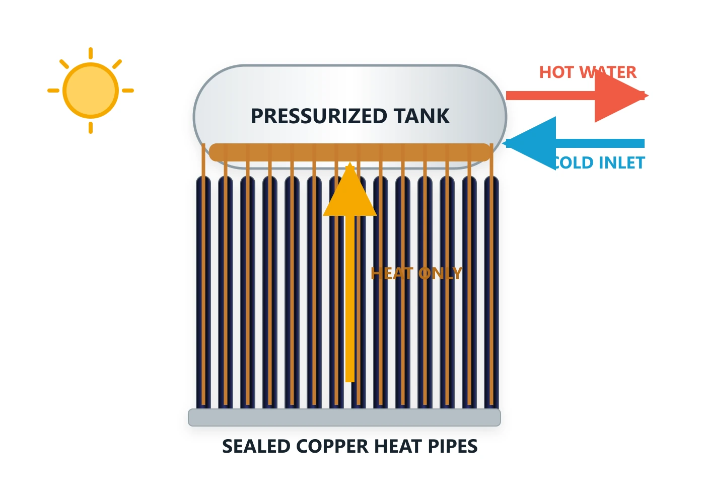
| Heat-pipe evacuated tube | Sealed heat pipe transfers heat to a manifold | Heat pipe may remain separate, but the manifold and connected circuit still need protection | Manifold, header fluid and dry connection face high-temperature exposure |
| U-tube direct-flow collector | System fluid travels through U-shaped tubes | Fluid product and concentration control freezing | U-tube geometry can retain fluid; confirm emptying behavior |
| Integrated thermosiphon heater | Tank sits above the collector | Direct water systems need climate-specific protection | Low demand can raise tank temperature and pressure |
| Pumped indirect collector field | Separate collector loop transfers heat through an exchanger | Supports antifreeze or drainback design | Requires coordinated vessel, controls, fluid and high-limit strategy |
The CASSKY solar thermal product overview separates complete water heaters from collector-only architectures for engineered arrays. Therefore, buyers should identify the exact fluid path rather than describe every product as a “heat-pipe system.”
When to Choose a Pressurized Antifreeze Loop
A pressurized loop may fit when:
- Roof geometry prevents complete gravity drainage.
- Collectors sit below or beside complicated pipe routes.
- The climate experiences prolonged freezing.
- The project can test and maintain the heat-transfer fluid.
- The plant room can accommodate the correct expansion vessel.
- Every component suits the fluid and temperature range.
- The owner accepts periodic fluid inspection.
However, the buyer should reject the proposal when the supplier cannot provide:
- Exact fluid product
- Concentration range
- Freeze and burst curves
- Expansion data
- Temperature limit
- Compatibility declaration
- Test method
- Maintenance procedure
A statement such as “40% glycol” does not provide enough information. Different products can use different base fluids, inhibitors and concentration curves.
When to Choose Drainback
A drainback system may fit when:
- Every collector and exterior line can drain by gravity.
- The reservoir remains in a protected location.
- The pump can overcome the initial lift head.
- The collector model permits drainback operation.
- The pipework avoids traps and sags.
- The controls support reliable filling and draining.
- The installer can prove complete drainage.
Drainback may not fit when:
- Architectural routes require long horizontal pipes.
- The collector contains sections that cannot empty.
- The roof lacks a continuous fall.
- The pump cannot provide the required start-up head.
- Noise from filling and draining conflicts with the building.
- The reservoir cannot accept the full drain volume.
Therefore, drainback suitability depends on geometry, not only climate.
Why Active Circulation Needs a Backup Assumption
Some systems start a pump when the collector approaches freezing. The circulation carries warmer tank water through exposed components.
This method may help during mild frost. However, it consumes stored heat and depends on sensors, controls, pumps and electrical power.
Consider the following counterexample:
- The controller detects low collector temperature.
- The pump starts normally.
- A grid outage then stops the pump.
- The ambient temperature remains below freezing for eight hours.
- Water stays trapped in the exterior pipework.
In this case, the circulation strategy cannot protect the system. Therefore, the design must state what happens during the specified power-outage duration.
Expansion Vessel and Pressure Boundaries
A pressurized solar loop must accommodate normal thermal expansion and the project’s adopted stagnation behavior.
The vessel selection needs:
- Total loop fluid volume
- Fluid expansion curve
- Cold fill temperature
- Maximum operating temperature
- Static height
- Cold fill pressure
- Maximum permitted pressure
- Relief-valve setting
- Vessel pre-charge
- Vessel acceptance factor
- Vaporizable collector volume
- Reserve volume
- Vessel temperature exposure
A domestic heating expansion vessel should not automatically substitute for a solar-rated vessel. The membrane, connection and temperature exposure may differ.
Moreover, the installer should not isolate the vessel from the collector loop while the collector remains active.
Component Temperature Review
The collector’s maximum temperature does not provide the only limit. Instead, the review should include every component that can see hot liquid or steam.
Request maximum temperature data for:
- Collector manifold
- Flexible connectors
- Pipe insulation
- Pump
- Flow meter
- Check valve
- Isolation valve
- Expansion vessel
- Pressure gauge
- Air separator
- Heat exchanger
- Sensor pocket
- Seals and gaskets
- Heat-transfer fluid
For example, a collector may tolerate stagnation while nearby pipe insulation does not. Therefore, the complete high-temperature zone must appear on the approved drawing.
Oversizing Creates a Stagnation Risk
Buyers sometimes increase the collector area to improve winter performance. However, the same field may produce excessive heat during summer.
The design should compare at least:
- Winter design load
- Annual average load
- Minimum summer load
- Maximum no-load duration
- Monthly solar resource
- Storage capacity
- Backup control
- Heat-rejection capacity
A larger field does not automatically provide a better project outcome. Instead, it can increase fluid ageing, relief events and maintenance.
Model-Specific Test Evidence
ISO 9806:2025 provides test methods for collector thermal performance, durability, reliability and safety. However, it does not certify the complete installed project.
Request the following for the exact collector model:
- ISO 9806 report identification
- Collector efficiency coefficients
- Stagnation temperature
- Maximum operating pressure
- Fluid volume
- Pressure drop
- Test fluid
- Permitted installation angle
- Relevant durability results
- Collector connection layout
Furthermore, confirm whether the report covers the exact tube, manifold and connection configuration in the quotation.
The 2026 IEA SHC Task 69 durability report discusses overheating, freezing, seals, insulation and long-term reliability across evacuated-tube architectures. It also reinforces an important procurement point: system reliability depends on materials, installation and protection strategy, not only initial thermal output.
Project Performance Evidence
Laboratory evidence and project acceptance answer different questions.
| Evidence type | What it supports | What it cannot prove |
|---|---|---|
| Collector laboratory test | Collector performance and applicable durability or safety results | Installed freeze protection |
| Fluid datasheet | Properties of a specified fluid and concentration | Actual field concentration |
| Expansion-vessel calculation | Design capacity under stated assumptions | Correct pre-charge or installation |
| Drainback drawing | Intended slopes and reservoir arrangement | Complete field drainage |
| Factory pressure test | Product integrity before shipment | Site pipework integrity |
| Commissioning test | Initial field settings and function | Long-term fluid condition |
| Field monitoring | Actual temperatures, pressures and operating events | Performance outside the monitored period |
For collector-field performance checks, ISO 24194:2026 provides procedures for comparing measured and calculated collector-field output. Nevertheless, a field-output check does not replace freeze and stagnation commissioning.
Freeze and Stagnation Commissioning Checklist
The commissioning plan should define measurable acceptance conditions.
Document review
Confirm:
- Exact collector model
- Approved hydraulic drawing
- Freeze-design temperature
- Power-outage design assumption
- Fluid product and concentration
- Expansion-vessel calculation
- Pressure schedule
- Relief setting
- Control sequence
- Stagnation response
- Drainback slope drawing where applicable
- Component temperature limits
Pressurized-loop checks
Record:
- Total charged fluid volume
- Fluid batch or product
- Measured concentration
- Calculated freeze point
- Calculated burst-protection point
- Fluid pH or other manufacturer-required condition
- Cold fill pressure
- Expansion-vessel pre-charge
- Relief-valve rating
- Static pressure
- Operating flow
- Air removal
- Leakage result
The commissioning record should use the heat-transfer-fluid manufacturer’s interpretation curve. A generic refractometer reading alone does not establish the protection temperature.
Drainback checks
Verify:
- Continuous fall from collectors to reservoir
- No pipe sags
- Complete drainage after pump shutdown
- Drainage time
- Reservoir operating level
- Reservoir capacity
- Pump start-up head
- Refill time
- Stable flow after refill
- Air return path
- Correct controller sequence
Do not approve a drainback system from a drawing alone. Instead, observe an actual fill-and-drain cycle.
Control checks
Test:
- Collector and tank sensors
- Pump start differential
- Pump stop differential
- Tank high limit
- Freeze-control function
- Heat-rejection output
- Alarm contacts
- Power-loss recovery
- Sensor-failure response
- Pump-failure response
The commissioning team should simulate sensor and control states safely. It should not expose equipment to destructive freezing or force uncontrolled stagnation.
Monitored acceptance
Record at least:
| Measurement | Acceptance basis |
|---|---|
| Collector-loop flow | Approved design value and supplier tolerance |
| Cold fill pressure | Approved pressure schedule |
| Hot operating pressure | Below the approved system limit |
| Fluid concentration | Selected product’s protection curve |
| Vessel pre-charge | Expansion-vessel calculation |
| Drainback time | Approved commissioning plan |
| Tank high limit | Approved control sequence |
| Heat-rejection function | Project operating sequence |
| Maximum observed temperature | Component limits |
| Alarm response | Approved cause-and-effect schedule |
Design Boundaries and Counterexamples
Suitable cold-climate boundary
A pressurized indirect system may suit a cold climate when the project confirms:
- Fluid protection temperature
- Fluid maintenance
- Vessel capacity
- Stagnation behavior
- Component temperature limits
- Backup power assumptions
- Installation quality
Unsuitable cold-climate boundary
A direct water system may not suit a site with prolonged freezing when it depends only on insulation or powered circulation.
Insulation slows heat loss. However, it does not create an unlimited freeze-protection period.
Drainback counterexample
A drainback reservoir may have enough volume. Nevertheless, a short horizontal section on the roof may retain water.
That trapped water can still freeze. Therefore, reservoir size alone does not prove drainability.
Antifreeze counterexample
An antifreeze loop may protect against −25°C. However, repeated stagnation may age the fluid and change its condition.
Consequently, cold-temperature protection does not prove high-temperature durability.
Summer hotel counterexample
A seasonal hotel may close during its sunniest month. In that case, annual occupancy can hide the controlling no-load condition.
The project should use the longest expected closure period, not only annual average demand.
Buyer RFQ Checklist
Include the following information in the RFQ.
Climate and operation
- Project city and country
- Design minimum temperature
- Hours below freezing
- Wind exposure
- Expected power-outage duration
- Summer minimum hot-water load
- Maximum no-load period
- Seasonal shutdown schedule
Collector and hydraulic design
- Exact collector type
- Exact collector model
- Collector quantity
- Fluid volume
- Field piping layout
- Static height
- Pipe diameters
- Pipe slopes
- Total loop volume
- Design flow
- Pressure drop
- Pump duty
Protection strategy
- Antifreeze or drainback basis
- Fluid product and concentration
- Freeze and burst-protection points
- Expansion-vessel data
- Relief setting
- Stagnation temperature
- Heat-rejection strategy
- Tank high limit
- Power-loss behavior
- Alarm requirements
Required documents
- Model-specific datasheet
- Collector test evidence
- Hydraulic drawing
- Fluid technical sheet
- Fluid compatibility statement
- Expansion-vessel calculation
- Control sequence
- Commissioning procedure
- Maintenance schedule
- Spare-fluid requirements
- Warranty exclusions
CASSKY’s support page provides public catalogs and a route for requesting model-specific technical files. Certificate, manual and test-report availability can differ by model and destination market.
Public Technical Resources
The following resources can support the project review:
- CASSKY Solar Thermal Product Catalog PDF
- ISO 9806:2025 collector test scope
- ISO 24194:2026 collector-field performance checks
- IEA SHC Task 69 durability and reliability report
- IEA SHC Task 26 stagnation report
- DOE solar thermal design guide
The CASSKY catalog and IEA/DOE reports provide public downloads. In contrast, buyers should request exact CASSKY model drawings, calculations, certificates and test documents.
Frequently Asked Questions
Are evacuated tubes freeze-proof?
No. The vacuum limits absorber heat loss, but water in manifolds, tanks and pipework can still freeze.
Does adding glycol solve stagnation?
No. Antifreeze addresses low-temperature protection. However, high stagnation temperatures can age the fluid.
Is drainback always safer?
Only when every exposed collector and pipe drains completely. Pipe sags, traps or unsuitable collectors can defeat the design.
Can the pump circulate warm water to prevent freezing?
It can support mild-weather protection. Nevertheless, power or pump failure can remove that protection.
Can a pressure relief valve control overheating?
No. It provides safety relief at its set condition. The system still needs a planned high-limit and stagnation strategy.
Should the buyer use the collector stagnation temperature as the pipe design temperature?
Not by itself. The engineer should map the expected liquid and steam zones and check every component’s applicable limit.
How often should the fluid receive testing?
Follow the fluid supplier and system manufacturer’s maintenance requirements. In addition, test after dilution, leakage, relief discharge or major service.
Request a Preliminary CASSKY Review
For an initial freeze and stagnation review, submit:
- Project location
- Design minimum temperature
- Power-outage assumption
- Collector type and quantity
- Summer minimum load
- Maximum no-load period
- Roof and piping drawings
- Storage volume
- Proposed fluid
- Static height
- Existing backup and heat-rejection equipment
- Required test and compliance documents
CASSKY can then review whether an integrated, pressurized indirect or collector-field configuration matches the project boundary. After configuration confirmation, the buyer can request applicable drawings, technical data and quotation support.